This device can also be called an EMF meter, as it can measure the relative strength of a field using a scale of 10 LEDs.
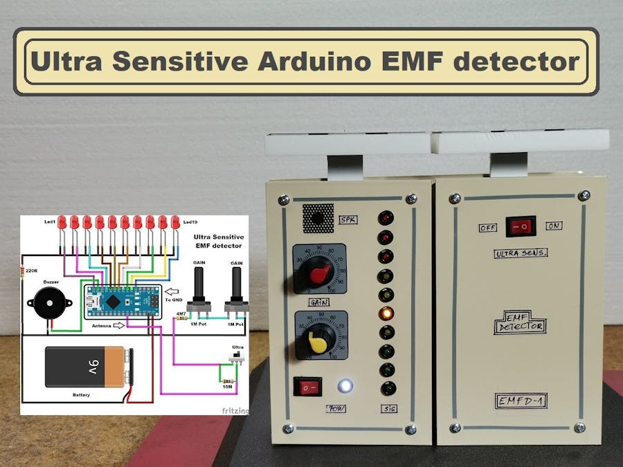
This time I will show you how to make a extremly sensitive electromagnetic field measurement device made with the Arduino microcontroller. Electromagnetic fields are a combination of invisible electric and magnetic fields of force. They are generated by many devices like power lines, kitchen appliances, mobile phones, computers, but they are also generated by natural phenomena like the Earth’s magnetic field. Еven the human brain emits extremely weak EMF signals that are thought to be potential mediators of telepathy.
The EMF detector introduced in this project is based on the Arduino Nano microcontroller and is extremely sensitive. This device can also be called an EMF meter, as it can measure the relative strength of a field using a scale of 10 LEDs. I modified the great code of Aaron ALAI's EMF detector project and Makezine magazine, so that instead of in line mode, the EMF strength is represented by a dot LED mode (only one LED is active at a time) reducing interferences, while we can also lower the reaction threshold in code. I also added an audible signal whose frequency changes depending on the field strength.
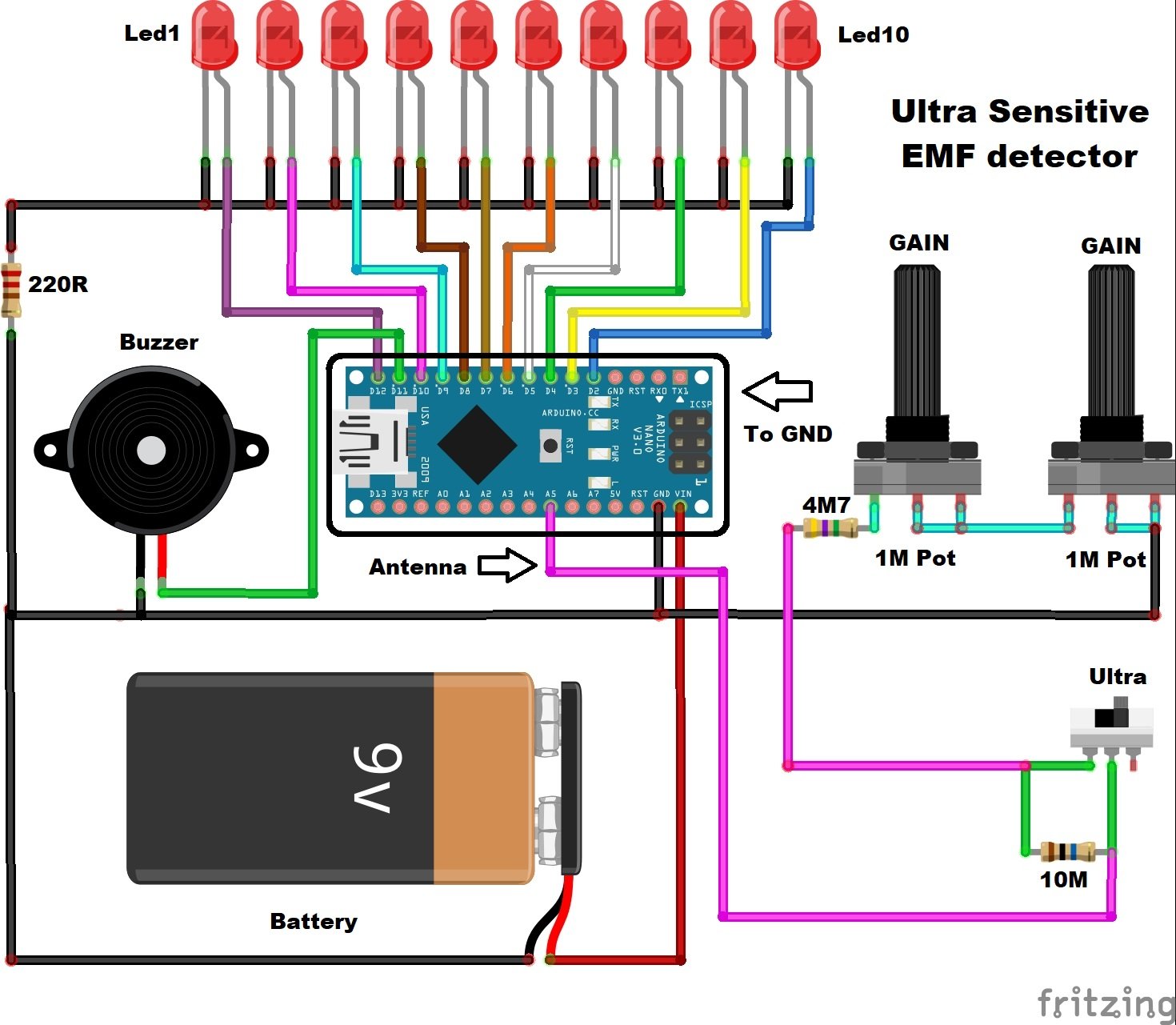
The device is relatively simple to build and contains only a few components:
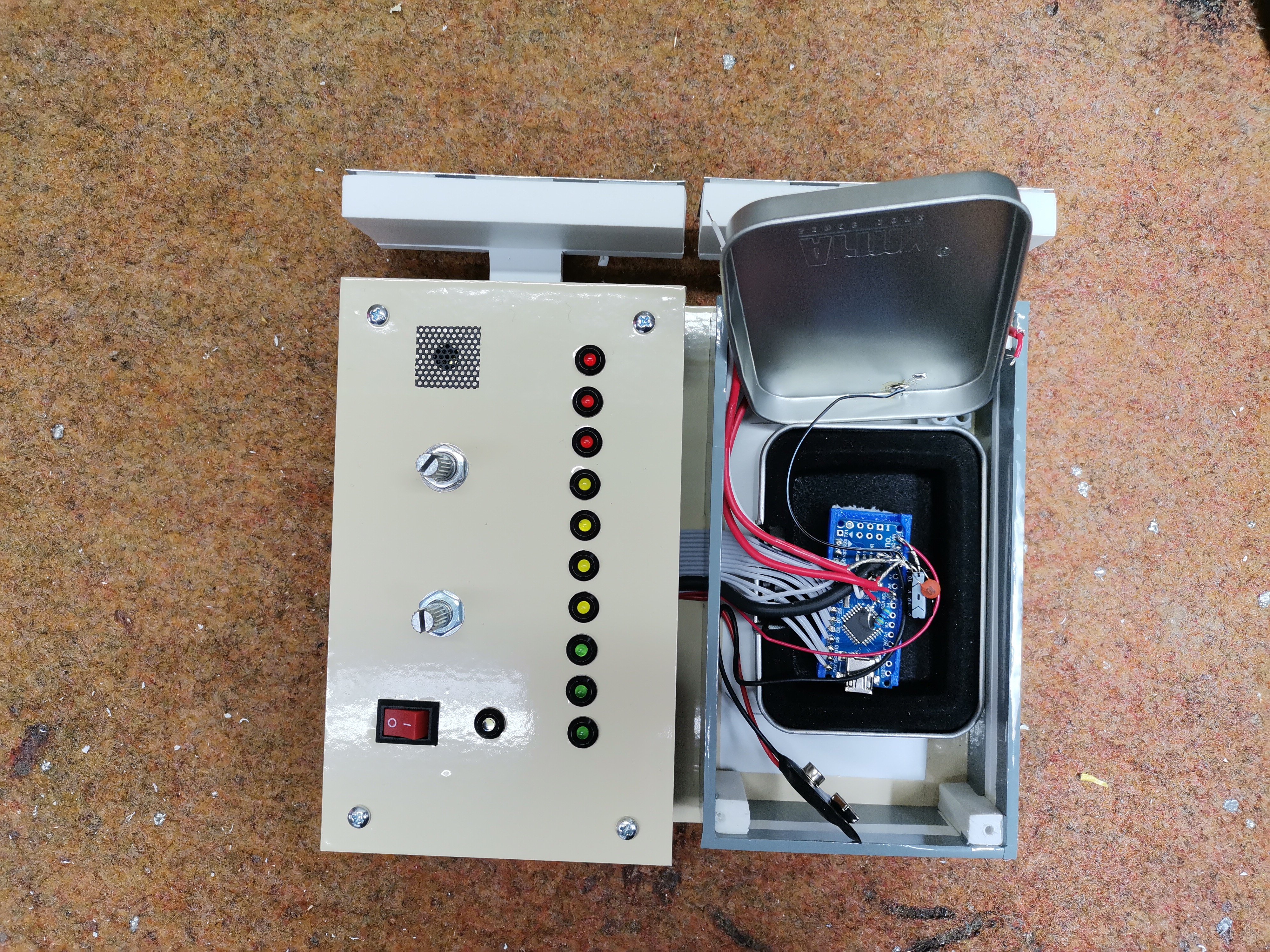
- Arduino nano microcontroller which is housed in this metal box
In the first version I mounted the Arduino in the same box along with the LEDs, potentiometers, and other electronics, but the instrument worked very unstable and was subject to self-oscillation. After some testing, I mounted the Arduino in a metal box that is grounded to the negative pole of the battery which greatly increases the stability and sensitivity. The detector also has an ULTRA MOD switch, and when it is turned on the sensitivity increases even more. Let me just emphasize that for work in this mode the device should be located in a room where there are no electrical appliances or installations at a distance of several meters from the detector.
And now let's explain how the device works in reality:
First we need to place the device in a place where there is no EMF radiation (preferably somewhere outdoors) and gradually turn the first potentiometer to the right. If the first LED is not activated yet, we continue with the second potentiometer, until the first diode lights up or flashes. Then turn the potentiometer back until the first LED goes out. First we need to place the device in a place where there is no EMF radiation (preferably somewhere outdoors) and gradually turn the first potentiometer to the right. If the first LED is not activated yet, we continue with the second potentiometer, until the first diode lights up or flashes. Then turn the potentiometer back until the first LED goes out.
This device can easily detect electromagnetic fields generated by power cables that are only under voltage and not connected to a consumer at a distance greater than 60cm in ultra sensitive mode as can be seen on the video. The EMF of my heater is detected at a distance of up to 100 centimeters or more. The electromagnetic field from power switch that turns on the lamp in my yard, can be detected from an incredible distance of 1.5 meters and more if set well in Ultra mode. Older CRT monitors are a very strong source of such radiation, so their field can be detected at a distance of 5m and more.
According to the LEDs and the frequency of the tone, the strength of the EM field is clearly visible. This type of sensitive EMF detector also are called a Ghost Detectors. As you can see in the video the detector presented is ultra sensitive and stable and is far better than the commercial EMF detectors that you can get at a relatively high price. However, in order to make this device successfully, you need to have some experience in the field of Electronics, especially in the way of grounding devices. If self-activation occurs without the presence of an EMF signal, we should reduce the value of resistor R1, but we should keep in mind that reducing this resistor also reduces the sensitivity of the detector.
And now a few words about the antenna:
In general, the shape and size of the antenna is best determined experimentally, so I left a place where a custom antenna can be connected. After a short test I created my antenna as the best in terms of sensitivity and compactness. In my case, it is a weak aluminum plate with dimensions of 7 by 3 centimeters. After a short test I created my antenna as the best in terms of sensitivity and compactness. In my case, it is a weak aluminum plate with dimensions of 7 by 3 centimeters.
This device can also be used as a lightning detector and in that case gives the best results with a wire with a length of fifty centimeters as an antenna. Finally, the device is built into a suitable box made of PVC with a thickness of 3 mm and coated with self-adhesive colored wallpaper.
// EMF Detector for LED Bargraph v1.0
// 5.12.2009
// original code/project by Aaron ALAI - [email protected]
// modified for use w/ LED bargraph by Collin Cunningham - [email protected]
// modified by Mirko Pavleski: Dot Led mode + Sound

#define NUMREADINGS 25 // raise this number to increase data smoothing

int senseLimit = 2; // raise this number to decrease sensitivity (up to 1023 max)
int probePin = 5; // analog 5
int val = 0; // reading from probePin

int LED1 = 12;  // connections
int LED2 = 10;  // to
int LED3 = 9;   // LED
int LED4 = 8;   // bargraph
int LED5 = 7;   // anodes
int LED6 = 6;   // with
int LED7 = 5;   // resistors
int LED8 = 4;   // in
int LED9 = 3;   // series
int LED10 = 2;  //

// variables for smoothing

int readings[NUMREADINGS];                // the readings from the analog input
int index = 0;                            // the index of the current reading
int total = 0;                            // the running total
int average = 0;                          // final average of the probe reading

void setup() {

  pinMode(2, OUTPUT);  // specify LED bargraph outputs
  pinMode(3, OUTPUT);
  pinMode(4, OUTPUT);
  pinMode(5, OUTPUT);
  pinMode(6, OUTPUT);
  pinMode(7, OUTPUT);
  pinMode(8, OUTPUT);
  pinMode(9, OUTPUT);
  pinMode(10, OUTPUT);
  pinMode(12, OUTPUT);

  Serial.begin(9600);  // initiate serial connection for debugging/etc

  for (int i = 0; i < NUMREADINGS; i++)
    readings[i] = 0;                      // initialize all the readings to 0
}

void loop() {

  val = analogRead(probePin);  // take a reading from the probe

  if(val >= 1){                // if the reading isn't zero, proceed

    val = constrain(val, 1, senseLimit);  // turn any reading higher than the senseLimit value into the senseLimit value
    val = map(val, 1, senseLimit, 1, 1023);  // remap the constrained value within a 1 to 1023 range

    total -= readings[index];               // subtract the last reading
    readings[index] = val; // read from the sensor
    total += readings[index];               // add the reading to the total
    index = (index + 1);                    // advance to the next index

    if (index >= NUMREADINGS)               // if we're at the end of the array...
      index = 0;                            // ...wrap around to the beginning

    average = total / NUMREADINGS;          // calculate the average

        int thisPitch = map (average, 50, 950, 100, 1500);
       tone(11, thisPitch,120);

    if (average > 50 && average < 150){                // if the average is over 50 ...
      digitalWrite(LED1, HIGH);   // light the first LED

    }
    else{                         // and if it's not ...
      digitalWrite(LED1, LOW);// turn that LED off

    }

    if (average >= 150 && average < 250){               // and so on ...
      digitalWrite(LED2, HIGH);
    }
    else{
      digitalWrite(LED2, LOW);
    }

    if (average >= 250 && average < 350){
      digitalWrite(LED3, HIGH);
    }

    else{
      digitalWrite(LED3, LOW);

    }

    if (average >= 350 && average < 450){
      digitalWrite(LED4, HIGH);

    }
    else{
      digitalWrite(LED4, LOW);

    }

    if (average >= 450 && average < 550){
      digitalWrite(LED5, HIGH);

    }
    else{
      digitalWrite(LED5, LOW);

    }

    if (average >= 550 && average < 650 ){
      digitalWrite(LED6, HIGH);

    }
    else{
      digitalWrite(LED6, LOW);

    }

    if (average >= 650 &&average < 750){
      digitalWrite(LED7, HIGH);

    }
    else{
      digitalWrite(LED7, LOW);

    }

    if (average >= 750 && average <850){
      digitalWrite(LED8, HIGH);

    }
    else{
      digitalWrite(LED8, LOW);

    }

    if (average >= 825 && average <900){
      digitalWrite(LED9, HIGH);
    }

    else{
      digitalWrite(LED9, LOW);

    }

    if (average > 900){
      digitalWrite(LED10, HIGH);

    }
    else{
      digitalWrite(LED10, LOW);

    }

    Serial.println(val); // use output to aid in calibrating
  }
}