ChatterBox is a secure off-grid mesh communication and location system that uses LoRa, meshing, encryption, and digital signatures. This project shows how to build a GPS-enabled motion sensing/relay node for your cluster.
This node will be able to alert you of motion (via mesh broadcast) and open/close a circuit remotely via encrypted mesh.
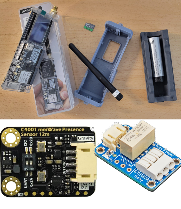
This ChatterBox mesh node is location aware (GPS) and uses a DFRobot mmWave radar module to sense motion. Optionally, you can add an Adafruit relay which will enable you to remotely open and close a circuit, or have the circuit open/close automatically when motion is detected. This node can also alert you of motion via mesh by automatically sending you a broadcast message when motion is sensed.
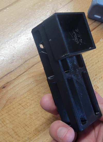
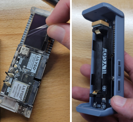
Step 1 - 3D Print an Enclosure
This case is a modified version (see downloads) of an original design from Alley Cat. It's a T-Beam case with added space for the DFRobot module, Adafruit Relay, and a channel for wires to pass through.
See the attached assembly doc for links to all these components.
In order to signal the relay, the ChatterBox node sends a HIGH signal to the pin. So, in theory, any relay switch that can be signaled with a HIGH could be used. Here, I use an Adafruit non-latching relay. The T-Beam has pins to support both 5V and 3.3V, but I have only personally used the 3.3V pin.
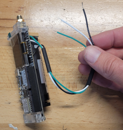
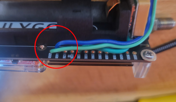
Step 3 - Solder VCC/GND/Signal wires to T-Beam
I typically use white for voltage, black for ground, and green for signal. As shown here, you'd connect:
Green -> Pin 46
White -> DC1 (3.3v 500mAh)
Black -> GND
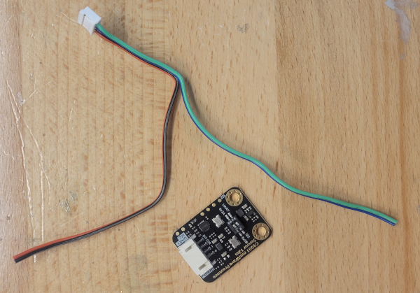
Step 4 - Prepare DFRobot Wires for Soldering
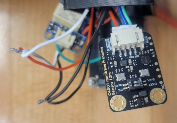
We will be using the white plug end of the DFRobot-included wires, but need to cut the black dupont adapters from the other end. You'll also want to separate the blue/green wires from the red/black, as shown in the image.
NOTE: Route the DFRobot blue/green wires through the relay housing (as shown a few steps down) before soldering. The DFRobot white plug will be sitting in the relay housing.
Step 5 - Attach DFR's SDA/SCL to T-Beam
In the wires provided with the DFRobot sensor:
Green (Data) goes to SDA
Blue (Clock) goes to SCL
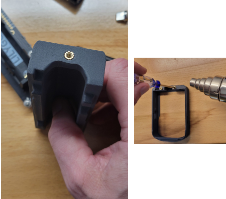
Step 6 - Press in Knurled Nuts
The 2 knurled nuts need to be heated/pressed into place, which can be done with a heat gun + screwdriver (as shown on the right) or, better, using a soldering iron with T3-sized tip designed for this (can be found on Amazon).
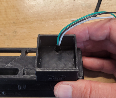
Step 8 - Route Wires To DFR/Relay Housing
Step 7 - Route Wires To DFR/Relay Housing
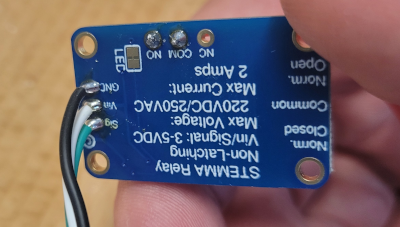
Step 9 - Connect VCC/GNS/Signal to Relay
Step 8 - Connect VCC/GNS/Signal to Relay
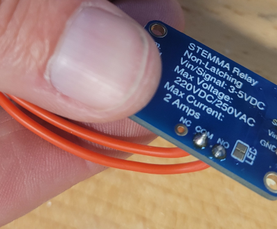
Step 10 - Connect the Circuit Wires
This is not required if you are building a Proximity-only node (no relay). Adding a relay is not required, it just gives your node an additional capability you may or may not use.
Here is where you choose to connect Normal Open (NO), Normally Closed (NC), or both. I'm using normally open.
If the above sentence doesn't make sense to you, don't build this (you should learn more about circuits before completing this project, or you could easily get injured or cause damage if you don't know what you're doing).
If you are actually going to connect this to a circuit for remote control, you need to understand the limitations and properties of whatever relay you are using here and make sure it is appropriate for your circuit.
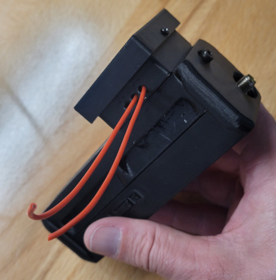
Step 11 - Insert the Relay Module and Route Wires
This is not required if you are building a Proximity-only node (no relay).
Insert the relay module into the housing and route the circuit wires out, so you can connect them to your circuit.
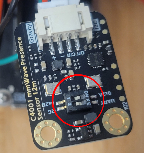
Step 12 - Set the DFR to use I2C
The DFRobot sensor has two switches.
- Controls the device's I2C address. Leave it at 0x2A
- Controls UART vs I2C. Switch this to I2C
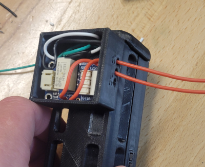
Step 13 - Connect DFR Power/GND to Relay's Power/GND
Connect the DFR's 3v/Gnd wires as shown above.
You will need to cut the relay's white and black wires, to splice them back together along with the DFR's +/Gnd.
You may want to do the wiring differently than what I've done here, but essentially both the DFRobot sensor and relay will be powered from the same connections on the T-Beam.
I simply twisted and soldered the wires as shown, and then slid/shrunk a heat shrink insulator over each set of wires.
Step 14 - Tuck the Components
Step 15 - Attach Relay Housing Cover
Step 16 - Install the Firmware
Optional (but good idea): Install a compatible SD card into the T-Deck
Flash the Node
Visit one of the following ChatterBox flash sites to install the T-Deck firmware.
Final Step - Onboard Your New Node
Your new node needs to be onboarded to your private ChatterBox cluster so you can securely interact with it. For more information about that, see the ChatterBox support site.