You can control this Arduino-based robot with hand gestures.
Tired of controlling your robot with a joystick? Ever thought of controlling it with your hand gestures. I wish I could control everything with my hand gestures. Sitting on a chair and controlling things like a BOSS. I loved the thought of it. So I finally came out with a hand gesture controlled robot that can follow the commands shown by hand. Sounds crazy but I promise it’s very simple.
Making a gesture control robot is actually very simple. This robot is an improvement of another DIY project, an RC car using RF module.
The robot is divided into two sessions, Transmitter and Receiver. The Receiver circuit is same as the one in the RC car project and there is a slight change in the transmitter circuit. Here we need to program the transmitter circuit to send hand gestures as commands. I will be using an Arduino as the programming platform to recognize the hand gestures with an accelerometer sensor. So let’s start making.
How Does It Work?
What is an Accelerometer?
In brief, an accelerometer is a three-axis acceleration measuring device. The one used here is ADXL335 and it has 3 axes (X Y Z).
The accelerometer is now there in almost all smartphones (No, we are not going to take it from a smartphone). You might have played motion games on your mobile (Eg Temple run). The character in the game moves left and right when you tilt your phone left and right respectively. It is done by the accelerometer.
How Does It Recognize the Hand Gestures?
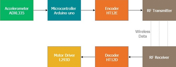
The brain of the robot is an Arduino Uno(Atmega32). It is fed with a set of code. The gestures/motion made by hand is recognized by the acceleration measuring device called accelerometer (ADXL335). The one we discussed earlier.
The Accelerometer shown above reads the X Y Z coordinates when we make hand gestures. It then sends the X Y Z coordinates to the Arduino. We don’t need the Z axis. We need only X and Y. The Arduino checks the values of coordinates and sends a 4bit data to the Encoder IC in accordance with the data received from the accelerometer. The Encoder passes the data to RF Transmitter. And the transmitted data is received by the RF Receiver. The receiver sends the 4bit data to Decoder IC which decodes it and passes to Motor Driver IC. Later the motor driver makes decision to turn the two motor in required direction
Making the Power Supply
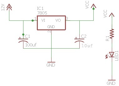
First, we will start with the power supply circuit. We need two power supply circuits. One for the transmitter and one for the receiver. The receiver circuit needs to be powered using a 12v supply (since I’m using a 12V motor). Transmitter circuit can be powered using 9v battery.
Using this diagram, wire up the supply circuit. You can also add an LED via a 1k resistor to indicate the state of the power supply.
- IC 7805 which regulates the 12v supply to 5v (if you can not get a 12v supply, you can use a 9v supply)
- 0.1uf & 470uf capacitor
- 1k resistor for status
- lED
NOTE: Use of heat sink for 7805 is suggested because we are dropping 7v (12-5 ). So lots of heat will be produced and could burn the regulator.
Making the Transmitter (Hand-Gesture Remote)
The receiver section consists of an accelerometer which detects the hand gestures. It then sends the data to the Arduino. Later, the Arduino sends data to the Encoder IC in accordance with the data received from the accelerometer, and the data is transmitted to the receiver.
Wire up the circuit using this diagram.
An illustration of the hand gestures controller circuit
Uploading the Code to Your Arduino
Upload the
hand gestures code to your Arduino.
Making the Receiver
/*
* Gesture Recognition Robot V1.1 - Avishkar
* Coder - Mayoogh Girish
* Website - http://bit.do/Avishkar
* This program lets you to control your robot with gesture made by your hand


                                ADXL335
                           ———————————¬
                          |Ø            Z   Ø|
                          |      X<---•      |
                          |           |      |
                          |           |Y     |
                          |           ∨      |
                          |                  |
                          |                  |
                          | O  O  O  O  O  O |
                           ———————————¬
                            ST Z  Y  X  -  +
                                                                            Right
                                                                              ∧
                                                                              |
                                                                              |
                                                               Forward <------|------>Backward
                                                                              |
                                                                              |
                                                                              ∨
                                                                             Left
          FOLLOW THIS INSTRUCTION TO CALIBRATE ROBOT

1) Upload ADXL3xx Sketch from examples [ File >> Examples >> Sensor >> AdXL3xx ]
2] Connect the sensor to arduino       [ X --> PIN A3
                                         Y --> PIN A2
                                         Z --> PIN A1 ]
3) Open serial                         [Ctlr + Shift + M]
4) Tilt the sensor in +X, -X, +Y ,-Y direction (forward, backward, left, right) and note down the required x y
5) Now change the
      #define forward_val xxx with new +X value
      #define backward_val xxx with new -X value
      #define left_val xxx with new +Y value
      #define right_val xxx with new -Y value

*/
//°°°°°°°°°°°°°°°°°°°°°°°°°°°°°°°°°°°°°°°°°°°°°°°°°°°°°°°°°°°°°°°°°°°°°°°°°°°°°°°°°°°°°°°°°°°°°°°°°°°°°°°°°°°°°°°°°°//

#define forward_val 340       // Change this value to change senstivity for forward direction     /-Default 340-/  *X*
#define backward_val 400      // Change this value to change senstivity for backward direction   /-Default 400-/   *X*
#define left_val 340          // Change this value to change senstivity for left direction      /-Default 340-/    *Y*
#define right_val 400         // Change this value to change senstivity for right direction    /-Default 400-/     *Y*

int GNDPin = A4; //Set Analog pin 4 as GND
int VccPin = A5; //Set Analog pin 5 as VCC
int xPin   = A3; //X axis input
int yPin   = A2; //Y axis input
int zPin   = A1; //Z axis input(not used)

int Q1=10,Q2=11,Q3=12,Q4=13; //Output pins to be connected to 10, 11, 12, 13 of Decoder IC

long x; //Variabe for storing X coordinates
long y; //Variabe for storing Y coordinates
long z; //Variabe for storing Z coordinates
void setup()
{
  Serial.begin(9600);
  pinMode(Q1,OUTPUT);
  pinMode(Q2,OUTPUT);
  pinMode(Q3,OUTPUT);
  pinMode(Q4,OUTPUT);
  pinMode(GNDPin, OUTPUT);
  pinMode(VccPin, OUTPUT);
  digitalWrite(GNDPin, LOW); //Set A4 pin LOW
  digitalWrite(VccPin, HIGH); //Set A5 pin HIGH
}
void loop()
{
  x = analogRead(xPin); //Reads X coordinates
  y = analogRead(yPin); //Reads Y coordinates
  z = analogRead(zPin); //Reads Z coordinates (Not Used)
    if(x<forward_val)      // Change the value for adjusting sensitivity
      forward();
    else if(x>backward_val) // Change the value for adjusting sensitivity
      backward();
    else if(y>right_val) // Change the value for adjusting sensitivity
      right();
    else if(y<left_val) // Change the value for adjusting sensitivity
      left();
    else
      stop_();
}

//Functions

void stop_()
{
  Serial.println("");
  Serial.println("STOP");
  digitalWrite(Q1,LOW);
  digitalWrite(Q2,LOW);
  digitalWrite(Q3,LOW);
  digitalWrite(Q4,LOW);
}
void forward()
{
  Serial.println("");
  Serial.println("Forward");
  digitalWrite(Q1,HIGH);
  digitalWrite(Q2,LOW);
  digitalWrite(Q3,HIGH);
  digitalWrite(Q4,LOW);
}
void backward()
{
  Serial.println("");
  Serial.println("Backward");
  digitalWrite(Q1,LOW);
  digitalWrite(Q2,HIGH);
  digitalWrite(Q3,LOW);
  digitalWrite(Q4,HIGH);
}
void left()
{
  Serial.println("");
  Serial.println("Left");
  digitalWrite(Q1,LOW);
  digitalWrite(Q2,HIGH);
  digitalWrite(Q3,HIGH);
  digitalWrite(Q4,LOW);
}
void right()
{
  Serial.println("");
  Serial.println("Right");
  digitalWrite(Q1,HIGH);
  digitalWrite(Q2,LOW);
  digitalWrite(Q3,LOW);
  digitalWrite(Q4,HIGH);
}
The receiver circuit consists of 2 ICs (HT12D decoder and L293D motor driver) and an RF receiver module.
Wire the circuit as per the above receiver schematic. There are 2 LEDs on the receiver board. One lights up when power is given to the receiver and the other when power is given to the transmitter. The led near the IC HT12D should be lit and this provides you a valid transmission(VT) when power is given at the transmitter. If not, there is something wrong with your connection or your RF TX/RX module. If you want to know more in detail about the receiver section, please read this article on how to create your own DIY Remote Control Car.
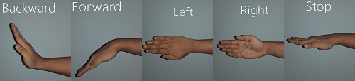
What Hand Gestures Will the Robot Recognize?
This robot is designed to recognize five sets of hand gestures. Forward, backward, left, right, and stop.
Enjoying steering your robot!!
Shrink It and Make It Permanent (Optional)
An Arduino UNO will be large and bulky on your hand. If you are deciding to make another project using the Arduino you will have to remove it and all of the connections made on it. You will lose your old work.
I don’t like doing that. So I came out with a more permanent solution. You can check out my other tutorial to learn how to shrink your Arduino project. Download the PCB layout for a standalone version of the picture above.
Watch this standalone video in which I have transferred the code to an Atmega8 MCU. I have only shown the outputs of MCU using LEDs.
And here is a working demo of my robot controlled with hand gestures!