Learn how you can create a pitch-only Theremin with a few components and an Arduino.
Interference is generally considered harmful, and particularly vulnerable to it are high impedance circuits. Electromagnetic interference (EMI) is generated by many household appliances that use switching power supplies and the number of these appliances in our homes is increased each and every day. The changing magnetic fields around us also generate a small voltage potential in our bodies — that can be easily checked if you touch the tip of an audio jack from any kind of amplifier.
Basically, the higher the impedance of a circuit, the higher the sensitivity of said circuit. An input of an amplifier has an input impedance of anywhere from about 600Ω for line input gear, up to 50-100kΩ for high impedance amplifiers for guitars. It’s amplifiers that sparked my interest. What could happen if I increased the input impedance to a hilariously large value, and try to utilize it for something? Trying this with an Arduino immediately came to mind, with it’s ADC input impedance of over 10MΩ, and I wanted to see what exactly could be done with it.
Theremin Experiments
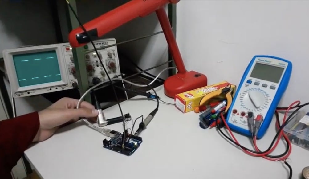
I turned on my Arduino, put a 30cm wire in the A0 connector, and fired it up with a bit of code so it can output its measurements to my computer.
void setup()
{
Serial.begin(9600); // initializes serial communication at 9600 bits per second
}
void loop() {
int sensorValue = analogRead(A0); //reads the value of A0
Serial.println(sensorValue); // prints out the value it reads.
}
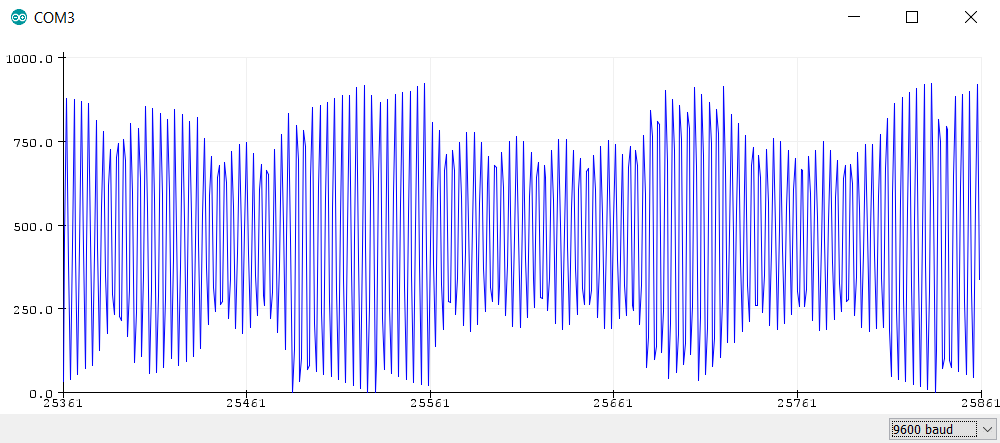
I uploaded the code, started the Serial Monitor tool, and voila! I noticed that every time I move my hand near the “antenna”, the values in the serial monitor increased accordingly. The Arduino is “feeling” the proximity of my hand.
With some additional code, I was confident I could make it run many devices that require sensing the proximity of other things, and this is especially effective at sensing the presence of conductors near the antenna. The idea that came to my mind was to stabilize this erratic signal and process it into a more “tame” signal. The possibilities were endless, and I wanted to make a functioning Theremin with it.
Readouts for the proximity of my hand to the Arduino.
Theremin Schematic
The hardware setup was very simple. I didn’t have any audiophile intentions while designing this, all I wanted was a simple way to hear the PWM output. Just a power transistor driving a speaker from the 5V supply. You might not even need to use cooling, as the currents in this case are so small, the TIP31C doesn’t heat up even without a heatsink.
Circuit diagram for Theremin with Arduino.
Full Code
Note: You can paste this directly into the Arduino IDE and it will work, but I included detailed comments to show you the principle of operation.
#define pitchAntenna A0 // Antenna input
#define output 3 // Frequency output

float peakPitch = 0;
float mappedPitch = 0;
float currPitch = 0; // Declaration of variables

void setup() {
  pinMode(pitchAntenna, INPUT);
  pinMode(output, OUTPUT); // Set pin modes
}
void loop()
  {
  for(int i = 0; i < 10; i++) // Get sum of 11 ADC readings
  {
    currPitch += analogRead(pitchAntenna);
  }
  currPitch /= 11;  // Divide them to get the average of 11 peaks

  if (currPitch > 512) // Get upper part of the frequency spectrum of the pitch input
  {
    if (currPitch > peakPitch) // Check if the current pitch is higher than the previous
      peakPitch = currPitch; // If it's higher, set the peak at the current pitch
    else mappedPitch = map(peakPitch, 550, 1023, 5000, 10); // Maps readings to the appropriate frequency range I want to use. The ADC readings from 550 to 1023 are mapped to frequencies between 5000 and 10Hz. I noticed that the antenna was having constant peaks at 400-500, irrelevant of the objects near it, so I used the map function to get rid of values under 550
  }
  else peakPitch = 0;
  if(mappedPitch > 100) // This works like a noise gate, increase if noise issues appear. Everything under the 100Hz range was triggered by random objects in the proximity of the Arduino, and this was added for stability
    tone(output, mappedPitch); // Set the frequency we acquired from the signal as the output frequency at  D3
  else noTone(output); // If the threshold isn't reached, this mutes the output
}
The Results
I concluded that the Arduino can utilize EMI for various purposes and that I can use it to make a simple Theremin with it. The video below shows the build in action.
Utilization of two antennas with a single Arduino, however, didn’t give the needed latency and stability we desire in a product like this because the ATMega328P chip simply doesn’t have the capability to process two inputs and two output parameters at the same time, so the idea was abandoned for sheer simplicity.
With two Arduinos however, one can implement a volume antenna too, which is a fully functional Theremin by then.
I hope you enjoyed this writeup just as much as I did, stay tuned for more awesome projects soon!