Have fun and learn at the same time with this Arduino based robot that solves mazes!
Modern robotics technologies are focused on developing self-navigating autonomous robots to automate our day-to-day processes. This means that most of the research focuses on improving sensors and algorithms to build flexible and accurate robots.
The maze solving robot — also known as a micro mouse — is designed to find a path without any assistance or help. As a type of autonomous robot, it has to decode the path on its own to solve the maze successfully. So it’s logic is quite different from the line following robot which follows a predetermined route. These types of autonomous mobile robots can be used in a wide variety of applications such as material handling, warehouse management, pipe inspection, and bomb disposal.
In this tutorial, I will show you how to build a simple Arduino maze solving robot using three ultrasonic sensors.
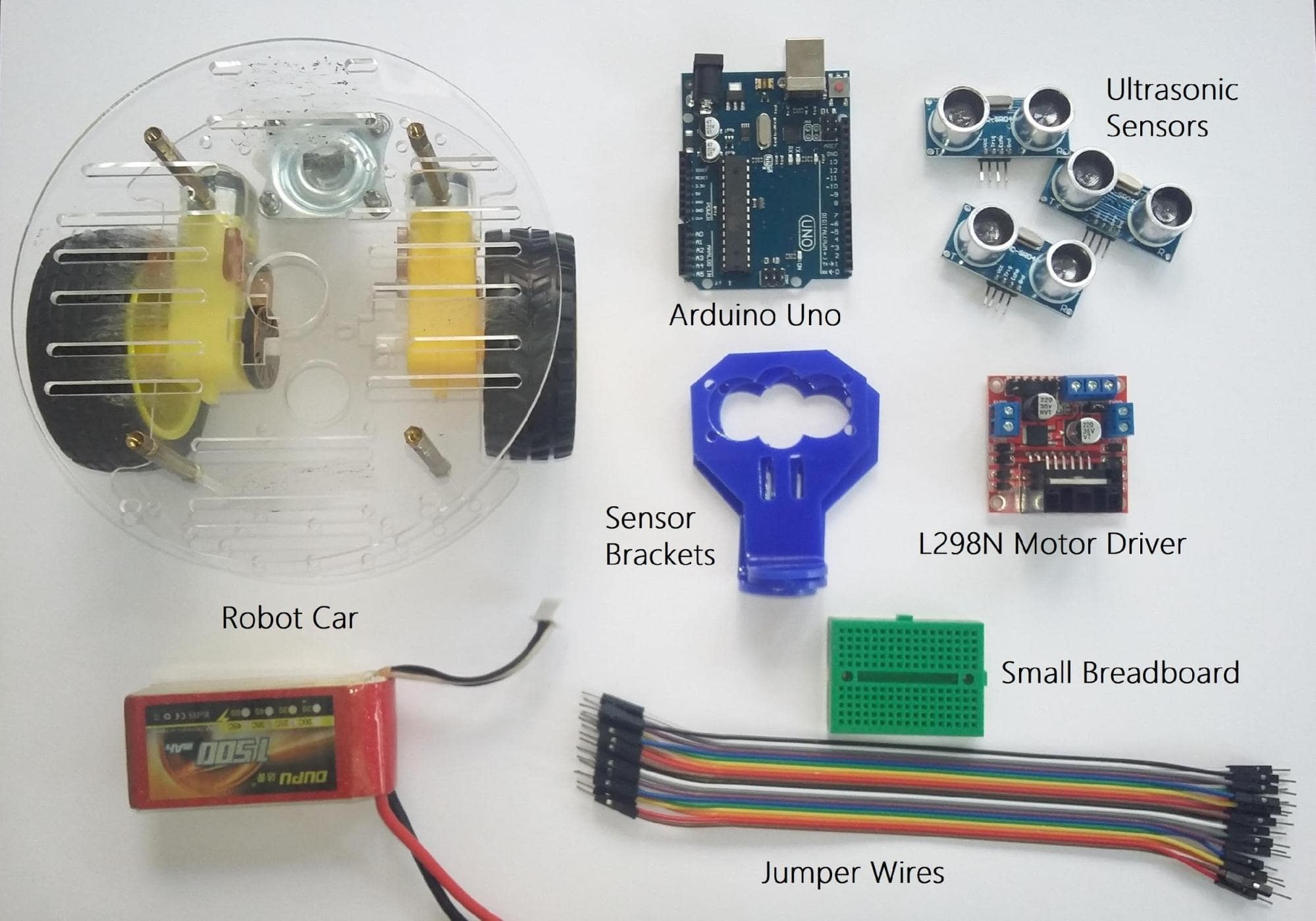
Required Components
- Robot car chassis
- Arduino Uno
- L298N Motor Driver
- 1500 mAh Lithium – Polymer (LiPo) battery
- 3 x Ultrasonic Sensors
- 3 x Sensor Brackets
- Small Breadboard and jumper wires
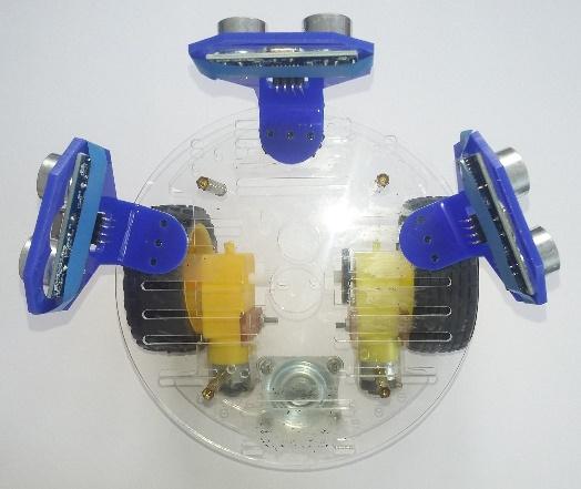
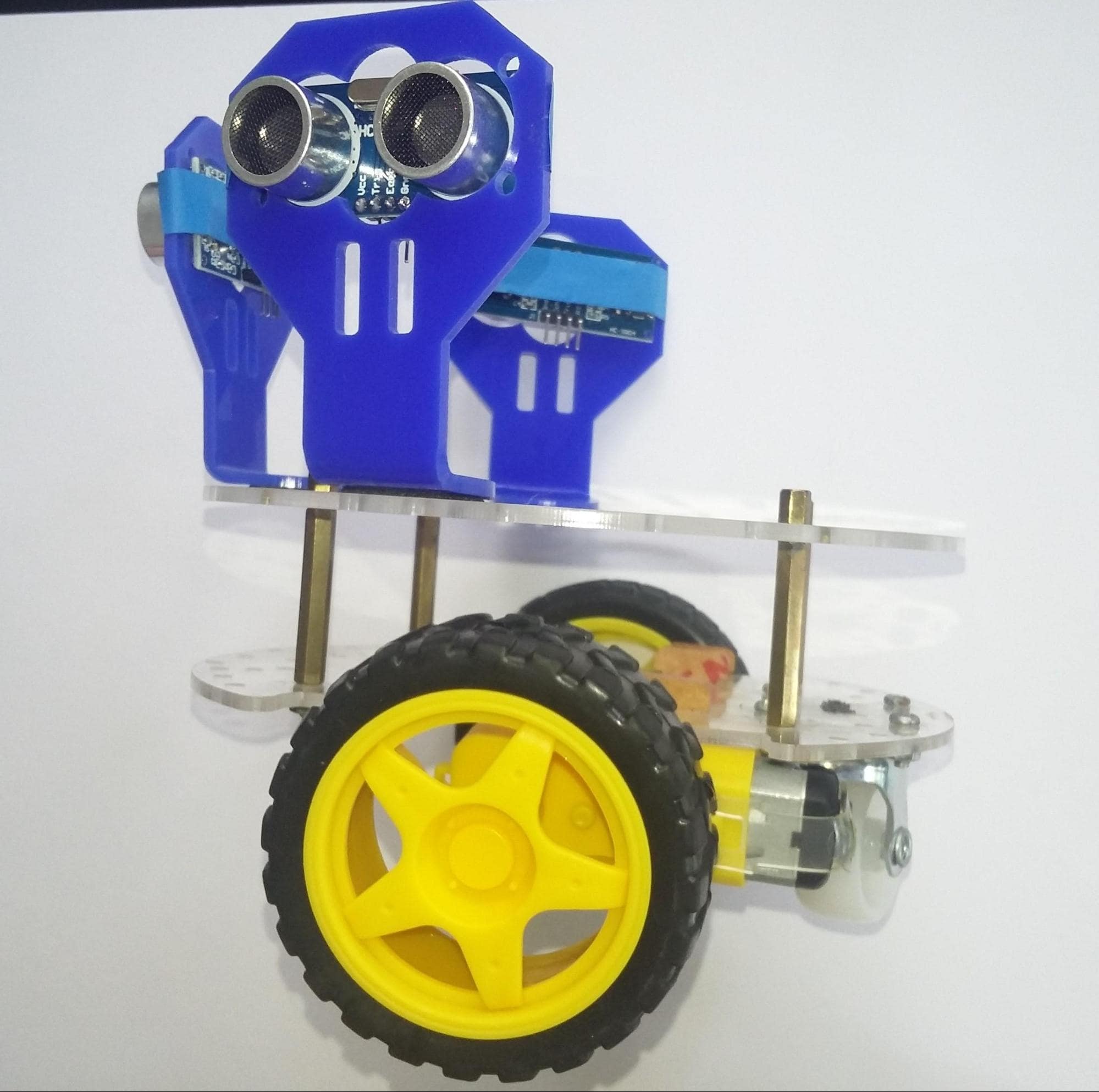
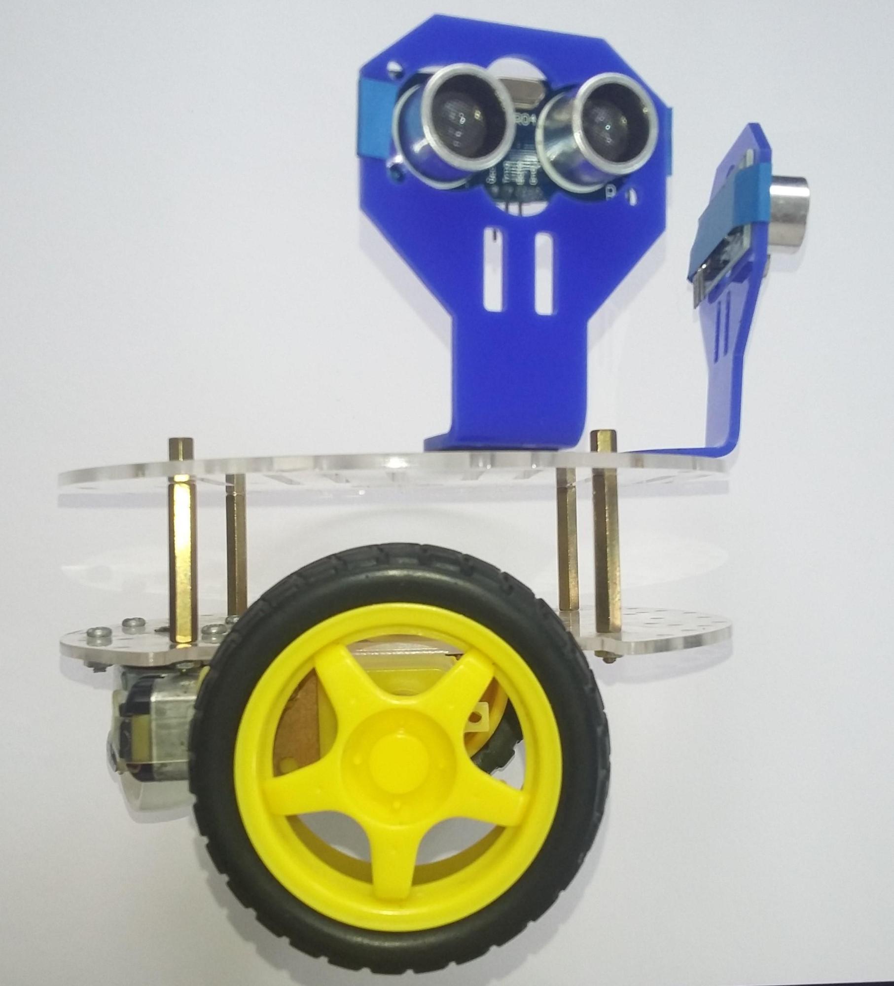
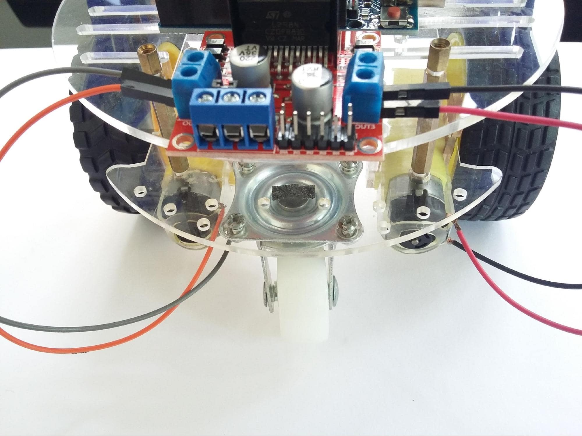
Assemble Chassis Parts and Ultrasonic Sensor Brackets
Assemble all the chassis parts tightly, using the proper nuts and bolts. Since the robot moves swiftly, make sure to have attached the sensor brackets properly and tightly.
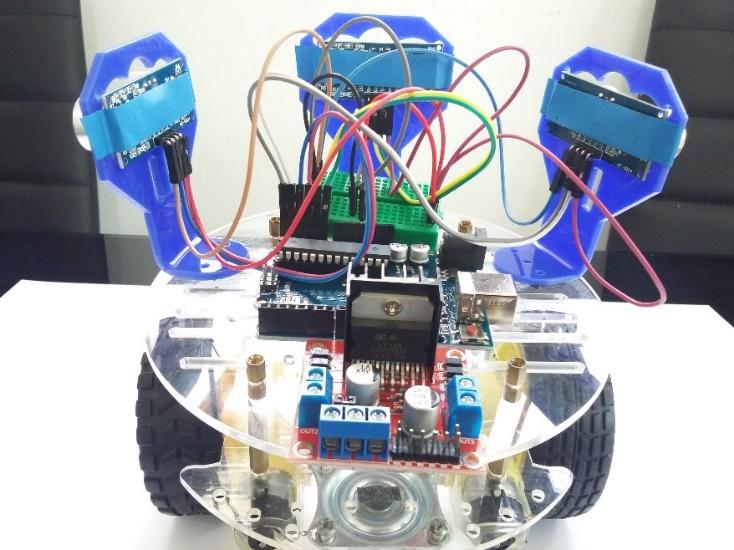
Attach All Components
Mount all the components on the top face of the robot chassis. Then mount the battery pack between the two plates. The configuration shown below allows you to wire all the components with the Arduino easily.
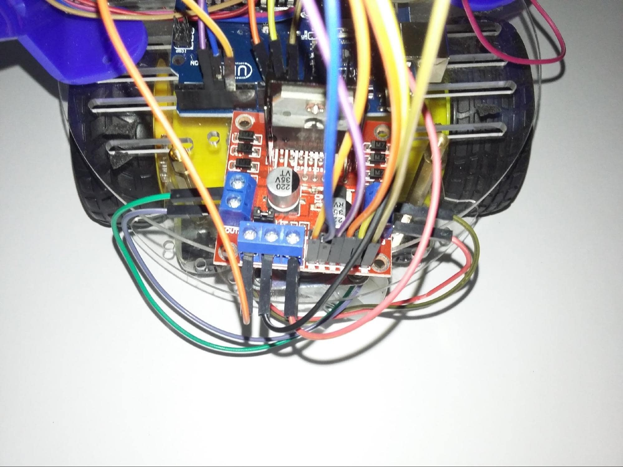
Wiring the Robot
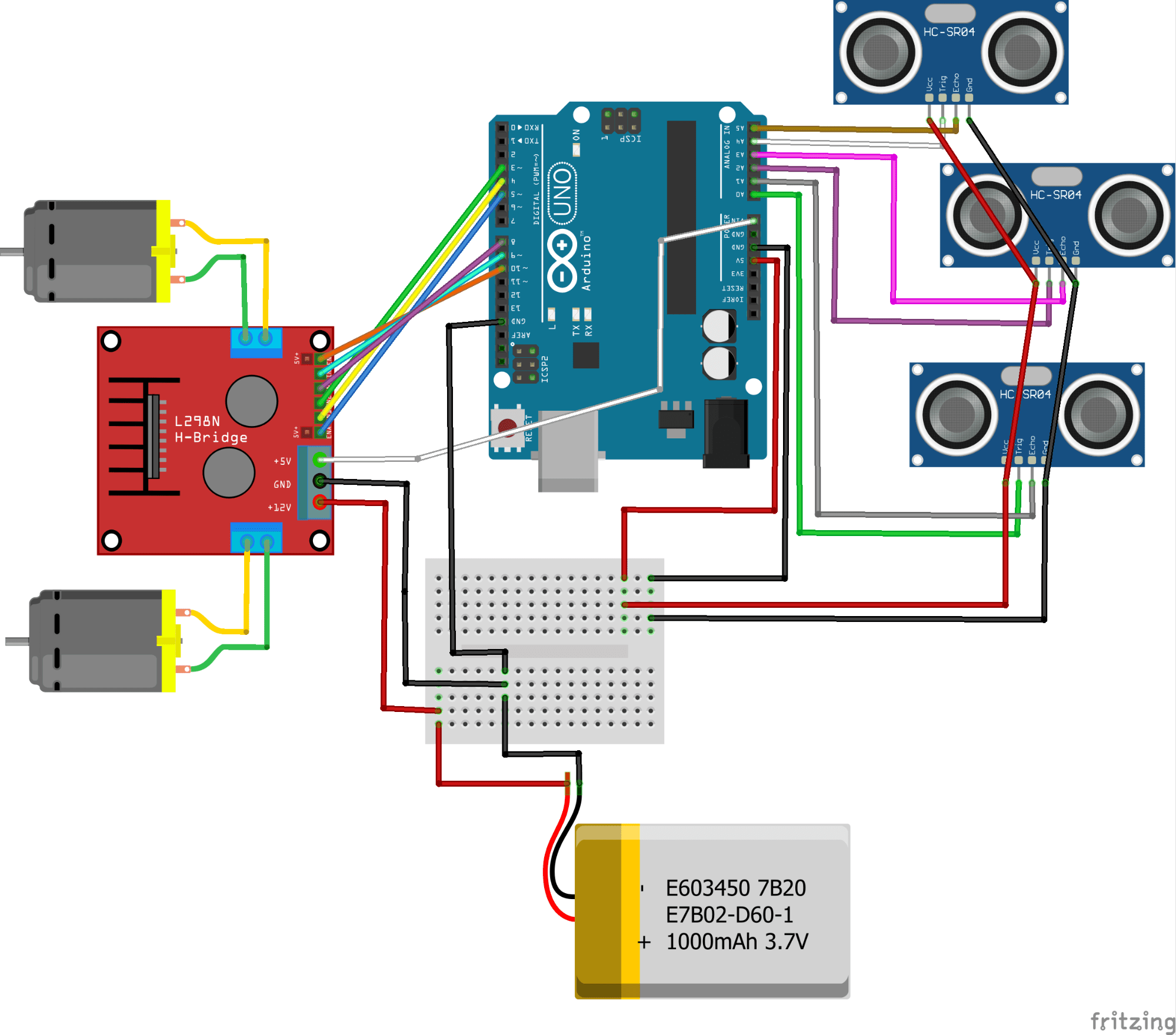
The wiring diagram is quite complex, but following the fritzing diagram below step by step and understanding each connection will help. This will allow you to debug your Arduino maze solving robot without much confusion.
Interfacing Ultrasonic Sensors to Arduino
Wire the trigger pin and echo pin of the sensors to analog pins of the Arduino. To power up the sensors, connect all the ground pins to a common ground rail and all the 5V pins to a common 5V rail on the breadboard.
Here, the ultrasonic sensors are basically the eyes of the robot which help it to find any obstacles around it. Ultrasonic sensors measure the distance to the obstacle for the robot to be able to navigate autonomously. You can implement your maze solving robot with just one or two ultrasonic sensors also, but having three sensors ensures more precise movements.
Interfacing the Motor Driver to Arduino
The motor driver has seven screw terminals, which makes the interfacing easy.
The L298N dual H-Bridge motor driver helps us to control the speed and direction of the two DC motors simultaneously. It acts as an interface between the motor and the Arduino. The motor driver has 4 input pins to control the rotational direction of the motor. ‘Enable A’ and ‘Enable B’ pins have the responsibility to enable and control the speed of the motors.
Arduino Code
This Arduino code can be used to solve a simple maze. There are a lot of ways in which you can design the logic to solve a maze, you can try experimenting with your own version after you finish this tutorial. The code will also need to adapt from maze to maze, and it usually involves a lot of trial and error to have the robot navigate successfully.
After assembling the robot, upload the Maze Solver source code to your Arduino from the IDE.
Now, let me walk you through some of the logic that the source code has.
- I have used the left side ultrasonic sensor as the supporting sensor to align the robot to the left sidewall. The robot always follows the left wall when solving the maze.
- If the front sensor detects an obstacle, the robot has to change direction immediately.
Mainly there are two types of situations that the robot must understand when solving the maze.
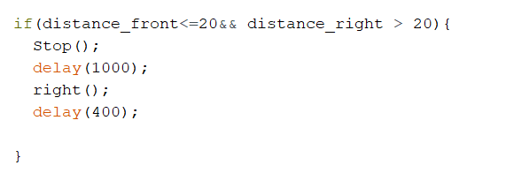
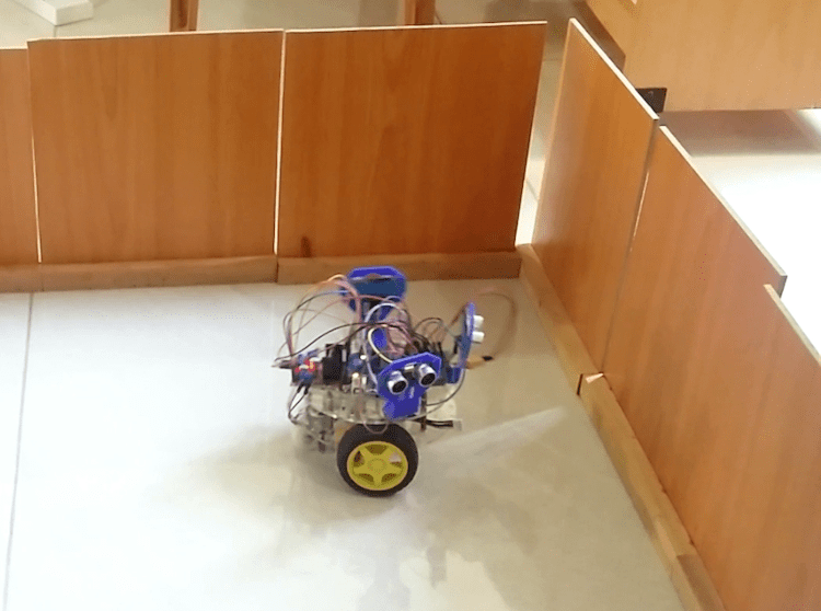
Situation 1: The Front Path is Blocked
In this type of situation, turn the robot 90 degrees to the right side. We can adjust the angle of rotation by changing the delay.
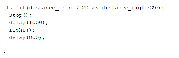
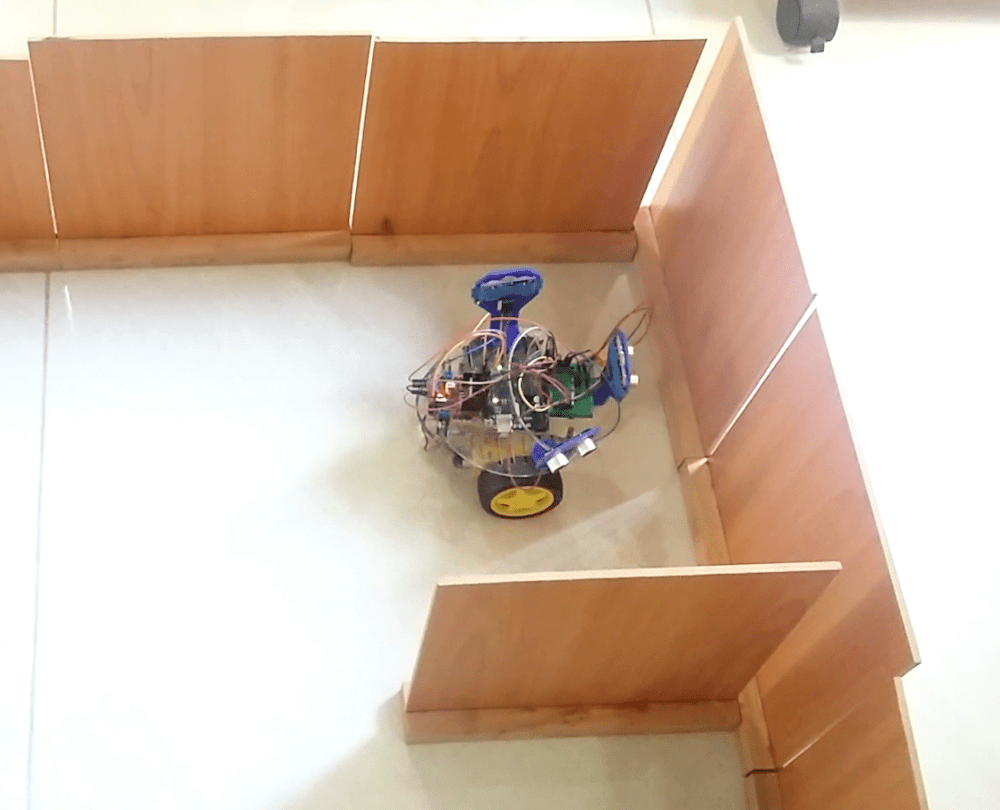
Situation 2: Both Front and Right Paths are Blocked
Here, the robot must turn 180 degrees to the right side. We can simply double the delay value to turn the robot 180 degrees. But remember, the delay values are different from robot to robot. It depends on your hardware, battery power as well as the speed of the robot.
Check out this demo video
Final Things to Keep in Mind for the Arduino Maze Solving Robot
As I have mentioned before, the performance of the robot depends upon your hardware, batteries as well as the environment (maze). So it involves a lot of trial and error before making the robot move smoothly. Here are some basic things to do before getting started:
- Check whether the robot navigates in forward, left and right directions properly.
- Check the sensor reading using the serial monitor to make sure that all the sensors are working properly.
- Do not connect external power sources when the board is getting power via USB cable.
- Make sure to use the lipo battery with extreme care. Do not charge the batteries unattended.