Control a servo motor with a joystick module by creating a transmitter and receiver with Arduinos and NRF24L01 modules!
In this project, we are going to control the servo motor using the NRF24L01 and Arduino. We will move the joystick on the transmitter side and, using the NRF24L01, we will send the joystick movement value to the receiver side where we will receive this value and move the servo motor using this value.
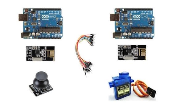
Required Components
The components required for this project are as follows:
- 2 Arduino
- 2 NRF24L01 modules
- Joystick module
- Servo motor
- Connecting wires
Required components for this project.
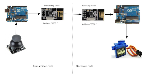
How the Servo Motor Control Works
On the transmitter side we have a joystick module, Arduino, and NRF24L01, while on the receiving side we have an NRF24L01, Arduino, and a servo motor.
When we move the joystick in the horizontal direction, the joystick module will send an analog value to the Arduino. We have set the NRF24L01 module in the transmitter mode, and it will send the joystick movement value at a specific address.
On the receiving side, we have set the NRF24L01 module in the receiving mode. We have given the same address at the receiving side at which the other NRF24L01 module is transmitting the data. So whenever the module will receive the data, the Arduino will read it and will move the servo motor according to it.
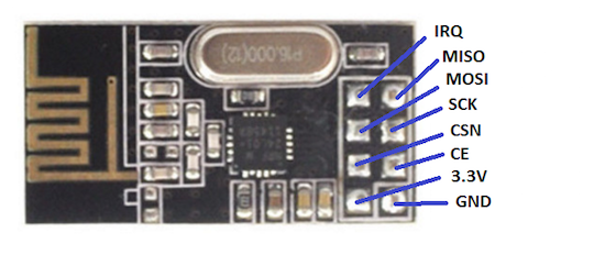
NRF24L01 Pinout
The power consumption of this module is very low. It consumes around 12mA of power during transmission, which is even lower than an LED.
This module operates at 3.3V, so don’t connect it directly to 5V of Arduino, as it can get damaged. The other pins of the NRF24L01 module are 5V tolerant, so you can connect these directly to Arduino.
The SCK, MOSI, and MISO pins are for SPI communication and the CSN and CE pins are for setting the standby or active mode and for setting the transmit or command mode.
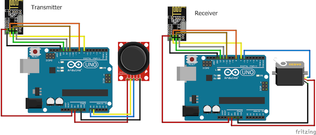
Circuit Diagram
The connections are a bit lengthy, so I will explain the connections for transmitter and receiver separately.
For the Transmitter
Make the connections for the transmitter side with the Arduino as follows:
- Connect the 3.3V pin of NRF24L01 with 3.3V of Arduino
- Connect the GND pin of NRF24L01 with GND of Arduino
- Connect the CSN pin of NRF24L01 with pin 8 of Arduino
- Connect the CE pin of NRF24L01 with Pin 7 of Arduino
- Connect the SCK pin of NRF24L01 with pin 13 of Arduino
- Connect the MOSI pin of NRF24L01 with pin 11 of Arduino
- Connect the MISO pin of NRF24L01 with pin 12 of Arduino
Then connect the joystick module with Arduino as follows:
- VCC of joystick module to 5V of Arduino
- GND of joystick module to GND of Arduino
- VER of joystick module to A1 of Arduino
- HOR of joystick module to A0 of Arduino
For the Receiver
On the receiver side, the connections for NRF24L01 with the Arduino are same as those made for the transmitter side. Make the connections for the servo motor with Arduino as follows:
- Red wire to 5V of Arduino
- Brown wire to GND of Arduino
- Yellow wire to Pin 6 of Arduino
Code for the Transmitter
#include <SPI.h>
#include <nRF24L01.h>
#include <RF24.h>
RF24 radio(7, 8); // CSN, CE
const byte address[6] = "00001";

int x_key = A1;
int y_key = A0;
int x_pos;
int y_pos;

void setup() {
  radio.begin();
  radio.openWritingPipe(address);
  radio.setPALevel(RF24_PA_MIN);
  radio.stopListening();

  pinMode (x_key, INPUT) ;
  pinMode (y_key, INPUT) ;
}

void loop() {
  x_pos = analogRead (x_key) ;
  y_pos = analogRead (y_key) ;
  radio.write(&x_pos, sizeof(x_pos));
  delay(100);
}
Code for the Receiver
#include <SPI.h>
#include <nRF24L01.h>
#include <RF24.h>
#include <Servo.h>
Servo servo;
RF24 radio(7, 8); // CSN, CE
const byte address[6] = "00001";
int servo_pin = 6;

void setup() {
  Serial.begin(9600);
  radio.begin();
  servo.attach (servo_pin ) ;
  radio.openReadingPipe(0, address);
  radio.setPALevel(RF24_PA_MIN);
  radio.startListening();
}

void loop() {
  if (radio.available()) {
    int x_pos ;
    radio.read(&x_pos, sizeof(x_pos));
    Serial.println(x_pos);
    x_pos = map(x_pos, 0, 1023, 0, 180);
    if (x_pos>400 && x_pos<600)
    {

    }
    else{
    servo.write (x_pos) ;
    }
  }
}
Code Breakdown and Explanation
First, include the libraries for the NRF24L01 and the servo motor.
#include <SPI.h>
#include <nRF24L01.h>
#include <RF24.h>
#include <Servo.h>
Then, define the pins where we have connected the CSN and CE pins of NRF24L01. After that, we initialize the address where we will send and receive the data. This address should be same on the transmitter as well as receiver side. This address can be any five-letter string.
RF24 radio(7, 8); // CSN, CE
const byte address[6] = "00001";
In the setup function for the transmitter, we set the address where we will send the data. Then we set the power amplification range to minimum because both our modules are closer to each other.
radio.openWritingPipe(address);
radio.setPALevel(RF24_PA_MIN);
For the receiver side, we used the following command and set the module to receive the data from this address.
radio.openReadingPipe(0, address);
In the loop function for the transmitter, we read from the joystick module and send the value at the address we set earlier.
radio.write(&x_pos, sizeof(x_pos));
The following command on the receiver side will get the data from the transmitter, and after mapping the data to 0-180, we will move the servo.
radio.read(&x_pos, sizeof(x_pos));