Learn how to build a LoRaWAN-based long-range wireless Arduino Robot using a Ra-02 Module and a two-wheeled Robot Kit.
LoRa Ra-02 | Arduino Nano |
|---|
3.3V | 3.3V |
Gnd | Gnd |
En/Nss | D10 |
G0/DIO0 | D2 |
SCK | D13 |
MISO | D12 |
MOSI | D11 |
RST | D9 |
Arduinos are great microcontrollers for applications such as home automation and robotics. They let us create prototypes easily using jumper wire cables. But what if you want to create wireless Arduino projects? It’s possible! In this tutorial, I’ll show you how to build a LoRaWAN-based long range wireless Arduino robot using an Ra-02 module and a two-wheel Arduino robot kit.
What is an Ra-02 Module?
The Ra-02 is a wireless communication module which is based on SEMTECH's SX1278 wireless transceiver. It has LoRa spread spectrum technology, which allows us to communicate wirelessly over the distance of 10,000 meters.
The SX1278 has a high sensitivity of -148 dBm with a power productivity of +20 dBm and a long transmission distance and high consistency.
As a quick refresher, dBm is the unit used to indicate power ratio. Tt is expressed in decibels (dB) with milliwatt (mW). The decibel (dB) is a dimensionless unit, used for measuring the ratio between two values, such as signal-to-noise ratio.
LoRa technology is great because of its anti-jamming capabilities and its low power consumption using smart wake-ups. This is what sets it apart from traditional modulation technologies. LoRaWAN could thus potentially be used to cover thousands of devices in the region for applications including meter readings, smart homes, and alarm equipment.
What is the Maximum Range With Ra-02?
The official description of Ra-02 LoRa module states it can reach a distance of 715km line of sight only i.e., if there are no obstacles between the node and gateway of the module. Many people have done experiments on just this and achieved communication between 212km ground to ground and up to 702km using weather balloons.
Ra-02 Features
- LoRa Spread Spectrum modulation technology
- Half-duplex communication
- Automatic RF signal detection
- Packet engine up to 256 bytes
- Constant RF + 20dBm-100mW voltage change
- Dual-row stamp-hole patch package
- Shielded housing
Ra-02 Specifications
- Communication range: 15km
- Sensitivity: down to -148dBm
- Programmable baud rate: up to 300kbps
- RSSI : 127dB
- Frequency: 433MHz
- Voltage: 1.8-3.7V
- Temperature: -40 - 80℃
With that information regarding the Ra-02 module, let’s dive into the build!
Required Hardware
- Arduino Nano x2
- Ra-02 LoRa module x2
- Push buttons x4
- L298N motor driver
- Jumper wires x4
- Breadboard x2
- Arduino 2-wheel robot
- Powerbank (For Arduino)
- 9V battery (For robot)
Note: In this project, I did not add an antenna. If you want to really test the long range feature of LoRa with the Ra-02, use its antenna.
The location of the external antenna on the Ra-02.
The Transmitter Remote for the Robot
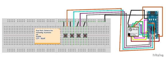
The transmitting side of the project uses an Arduino Nano, an Ra-02 LoRa module, and four pushbuttons. The Fritzing diagram for connections between the Nano and Ra-02 is shown below. I used a double breadboard for these connections and it worked well.
Connections between the Nano, Ra-02, and push buttons.
Here is a table showing the specific pin connections between the Ra-02 and the Nano.
LoRa Ra-02 | Arduino Nano |
|---|
3.3V | 3.3V |
Gnd | Gnd |
En/Nss | D10 |
G0/DIO0 | D2 |
SCK | D13 |
MISO | D12 |
MOSI | D11 |
RST | D9 |
Here is a table showing the specific pin connections between the push buttons and the Nano.
Push buttons | Arduino Nano |
|---|
Button 1 | D4 |
Button 2 | D5 |
Button 3 | D6 |
Button 4 | D7 |
The Receiver Side of the Robot
Make the connections for the receiver part of the robot as shown below. You can use any robot chassis kit you can get of Amazon. Assemble it and make the following connections.
L298N | Arduino Nano |
|---|
IN 1 | D4 |
IN 2 | D5 |
IN 3 | D6 |
IN 4 | D7 |
LoRa Ra-02 | Arduino Nano |
|---|
3.3V | 3.3V |
Gnd | Gnd |
En/Nss | D10 |
G0/DIO0 | D2 |
SCK | D13 |
MISO | D12 |
MOSI | D11 |
RST | D9 |
Connections for the receiver side of the project.
Source Code
Upload the source code given below on both the TX and RX side of the Arduinos.
Receiver Code
#include <SPI.h>
#include <LoRa.h>
const int RightMotorF= 4;
const int RightMotorB= 5;
const int LeftMotorF= 6;
const int LeftMotorB= 7;
String  msg="";

void setup() {
  pinMode(RightMotorF,OUTPUT);
  pinMode(RightMotorB,OUTPUT);
  pinMode(LeftMotorF,OUTPUT);
  pinMode(LeftMotorB,OUTPUT);
  Serial.begin(9600);
  while (!Serial);

  Serial.println("LoRa Receiver");

  if (!LoRa.begin(433E6)) {
    Serial.println("Starting LoRa failed!");
    while (1);
  }
}

void loop() {
  // try to parse packet
  int packetSize = LoRa.parsePacket();
  if (packetSize) {
    // received a packet
    //Serial.print("Received packet '");

    // read packet
    while (LoRa.available()) {
     // Serial.print((char)LoRa.read());
      msg=(char)LoRa.read();
     Serial.println(msg);
      if(msg=="u")
    {
  digitalWrite(RightMotorB,LOW);
  digitalWrite(LeftMotorB,LOW);
  digitalWrite(RightMotorF,HIGH);
  digitalWrite(LeftMotorF,HIGH);

  Serial.println("Motor forward");
  }
  else if(msg=="d")
  {
  digitalWrite(RightMotorB,HIGH);
  digitalWrite(LeftMotorB,HIGH);
  digitalWrite(RightMotorF,LOW);
  digitalWrite(LeftMotorF,LOW);

  Serial.println("Motor Back");
  }
   else if(msg=="l")
  {
  digitalWrite(RightMotorB,LOW);
  digitalWrite(LeftMotorB,HIGH);
  digitalWrite(RightMotorF,HIGH);
  digitalWrite(LeftMotorF,LOW);
  Serial.println("Left");
  delay(300);
  digitalWrite(RightMotorB,LOW);
  digitalWrite(LeftMotorB,LOW);
  digitalWrite(RightMotorF,LOW);
  digitalWrite(LeftMotorF,LOW);
  }
   else if(msg=="r")
  {
  digitalWrite(RightMotorB,HIGH);
  digitalWrite(LeftMotorB,LOW);
  digitalWrite(RightMotorF,LOW);
  digitalWrite(LeftMotorF,HIGH);
  Serial.println("right");
  delay(300);
  digitalWrite(RightMotorB,LOW);
  digitalWrite(LeftMotorB,LOW);
  digitalWrite(RightMotorF,LOW);
  digitalWrite(LeftMotorF,LOW);
  }
 }

    // print RSSI of packet
   // Serial.print("' with RSSI ");
   // Serial.println(LoRa.packetRssi());
  }
}
Transmitter Code
#include <SPI.h>
#include <LoRa.h>

int counter = 0;
int up_button     = 4; // UP
int down_button   = 5; // Down
int left_button   = 6; // LEFT
int right_button  = 7; // RIGHT
int buttons[]={up_button, down_button,left_button,
               right_button};

void setup() {
  Serial.begin(9600);
  for(int i; i <4 ; i++)
     {
         pinMode(buttons[i],INPUT);
         digitalWrite(buttons[i],HIGH);
     }


  while (!Serial);

  Serial.println("LoRa Sender");

  if (!LoRa.begin(433E6)) {
    Serial.println("Starting LoRa failed!");
    while (1);
  }

  LoRa.setTxPower(20);

}

void loop() {
  //Serial.println("Sending packet: ");
 // Serial.println(counter);

  // send packet
//  LoRa.beginPacket();
 // LoRa.print("hello ");
 // LoRa.print(counter);
  if(digitalRead(up_button)==LOW)
      {
      LoRa.beginPacket();
      LoRa.print("u");
      Serial.println("UP Button Pressed");
      delay(300);
      LoRa.endPacket();

      }
   else if(digitalRead(down_button)==LOW)
      {
      LoRa.beginPacket();
      LoRa.print("d");
      Serial.println("down Button Pressed");
      delay(300);
      LoRa.endPacket();
      }
         else if(digitalRead(left_button)==LOW)
      {
        LoRa.beginPacket();
      LoRa.print("l");
      Serial.println("left Button Pressed");
      delay(300);
      LoRa.endPacket();

      }
         else if(digitalRead(right_button)==LOW)
      {
        LoRa.beginPacket();
      LoRa.print("r");
      Serial.println("right Button Pressed");
      delay(300);
      LoRa.endPacket();

      }
      //delay(1000);
 // Serial.println("waiting....");
 // LoRa.endPacket();

  counter++;

 // delay(5000);
}
The final build ready to go!