In this tutorial, learn to simulate Arduino projects using Proteus by interfacing a seven-segment display and DC motor.
What is Proteus and How Does it Compare to Other Simulation Software?
Proteus is a simulation and electronic design development tool developed by Lab Center Electronics. It is a very useful tool as it ensures that the circuit design or firmware code is working properly before you begin to physically work on it.
It has an extensive number of components in its library which can be used to virtually design your circuit. The designs you make can be easily compiled and debugged through Proteus’s virtual meters (voltmeter and ammeter), oscilloscope, serial monitor, and more.
I prefer Proteus for Arduino project simulation because of its extensive collection of libraries. However, it is not only limited to simulation — you can also make PCB designs with it.
TinkerCAD is also another tool that can be used for simulation.Developed by AutoDesk, it is a cloud-based software which is only limited to Arduino simulation.
If you are a beginner to Arduino and circuit design, then I recommend you try out TinkerCAD. If you want to work on a cool project which involves some circuit design, I recommend Proteus.
How to Install an Arduino Library in Proteus
Proteus doesn’t come with an inbuilt Arduino library, so you have to install it externally. Follow the steps below to install it on your PC.
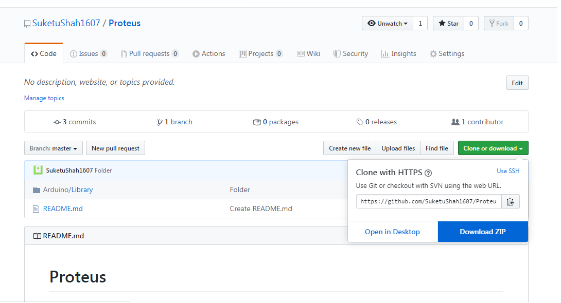
1. Download all library-related files from GitHub.
2. Extract the zip file and navigate to Proteus-master\Arduino\Library.
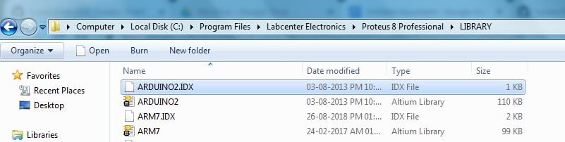
3. Copy both of the files and paste them in one of the following paths:
C:\Program Files\Labcenter Electronics\Proteus 8 Professional\LIBRARY
or
C:\Program Files\Labcenter Electronics\Proteus 8 Professional\Data\LIBRARY
Now, open Proteus and check whether the Arduino board libraries are installed properly or not.
4. In Proteus, create a new project.
Create a new project in Proteus.
5. Decide where you would like to save your project.
Choose where to save your project.
Click Next once you are done and select the appropriate page layout according to your needs.
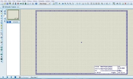
6. After finishing the settings, you will land on the empty workspace. Here, you can place components from the library.
The workspace where you can place components.
Getting Started in the Proteus Workspace
Select the op-amp symbol, which changes the mode to component mode. Then click P, which will cause a list of components to pop up. Here, you can find all types of components and footprints for simulation.
Set your mode to component mode.
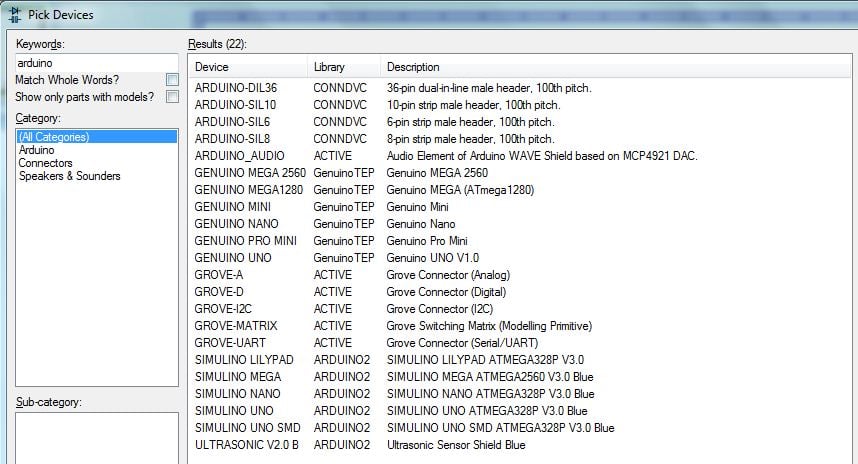
Search for Arduino in the component list. All Arduino related boards and connector libraries will display. If none of the files display on your machine, you can repeat re-installing the Arduino library.
Select Arduino UNO, as you will be programming on this board in this example.
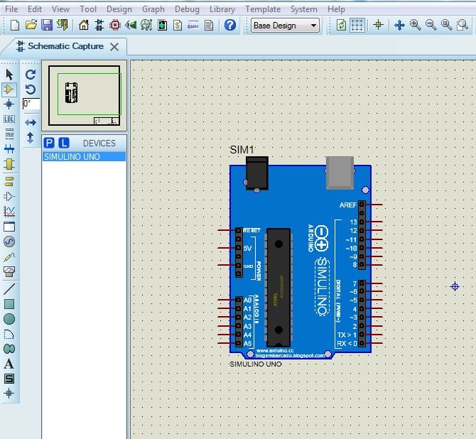
After selecting the library and clicking OK, click the spot on the workspace where you would like to drop the board.
Place your Arduino by clicking the desired spot on your workspace.
How to Simulate Projects
I’m going to show you how to simulate your Arduino projects with an example using a seven-segment up-counter and Arduino. The code and hardware will be presented in the next section, so for time being, just focus on simulation.
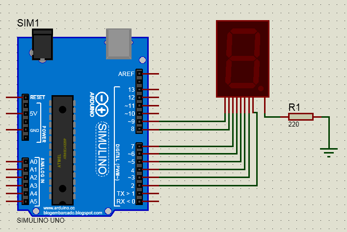
First, mimic the wiring connections shown below in Proteus.
You can find all components from the list to complete hardware wiring. To connect any two components through a wire, left-click on one of the connector ends and drag the mouse towards another end to connect it.
Create connections by left clicking and dragging the connector path between components
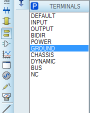
Power pins, such as Vcc and Gnd, can be found in Terminal Mode
Once you are done making the connections, upload the hex file of the code to your Arduino. To do this, open the code you downloaded from GitHub in Arduino IDE.
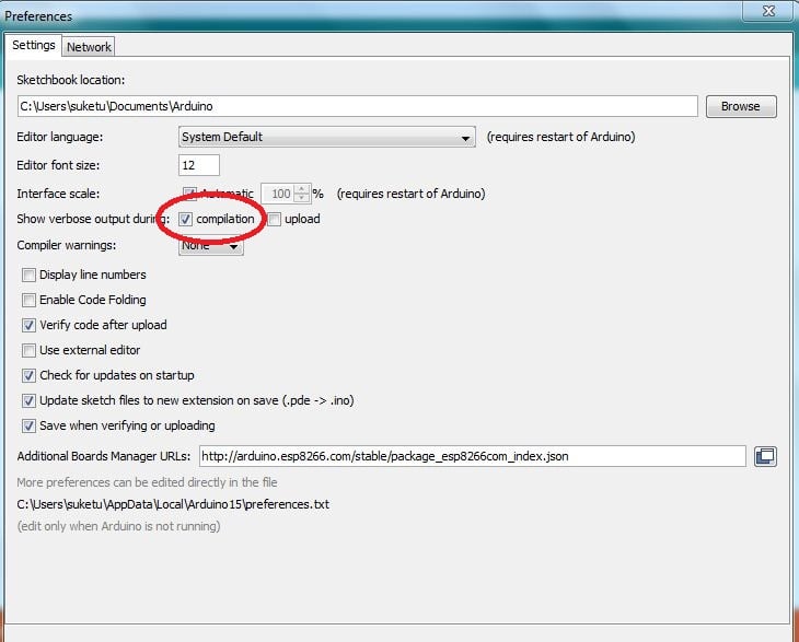
Check whether the compilation option is checked to generate the hex file. It can be found from File —> Preferences.
Compile the code and copy the hex file-path.
Double click on the Arduino board to insert the hex file of code.
After inserting a hex file, you can start the simulation by pressing the play key.
Interfacing a Seven-segment Display to Perform Up-counting
As the name suggests, a seven-segment display is a combination of 7 LEDs which are used to display alphabets and numbers. It also has a small dot LED known as dp.
Seven-segment display pinout.
All LEDs in a seven-segment display are named alphabetically, making it very easy for a programmer to display a number or alphabet.
Here, connect all LEDs to the digital pins of the Arduino. A HIGH state from the digitalWrite function will turn ON an LED and vice versa. Below is a chart to display numbers using a common cathode seven-segment LED.
| a | b | c | d | e | f | g |
|---|
0 | ON | ON | ON | ON | ON | ON |
|
1 |
| ON | ON |
|
|
|
|
2
| ON | ON |
| ON | ON |
| ON |
3 | ON | ON | ON | ON |
|
| ON |
4 |
| ON | ON |
|
| ON | ON |
5 | ON |
| ON | ON |
| ON | ON |
6 | ON |
| ON | ON | ON | ON | ON |
7 | ON | ON | ON |
|
|
|
|
8 | ON | ON | ON | ON | ON | ON | ON |
9 | ON | ON | ON |
|
| ON | ON |
Note: Empty space = OFF
As far as programming is concerned, you can display a single-digit number and ascend it at fixed intervals. I have made a function to display a single-digit number.
DisplayNumber(num);
Here is up-counter logic which will be repeated again and again, using a void loop().
void loop()
{
  for(i=0;i<=9;i++)
  {
    DisplayNumber(i);
    delay(1000);
  }
}
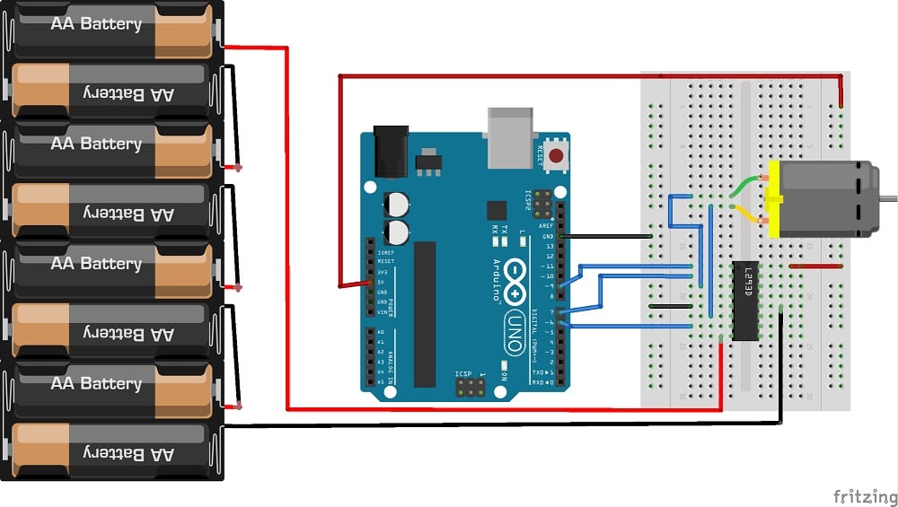
Interfacing a DC Motor With Arduino Using an L293D IC
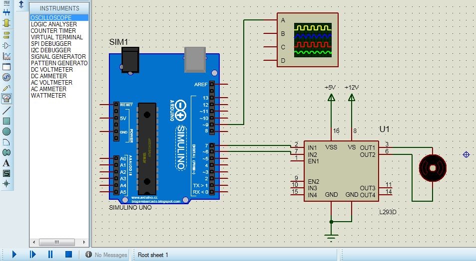
This exercise shows you how to simulate a DC motor and observe PWM waves on the oscilloscope using Proteus. A PWM signal from the Arduino is required to change the DC motor’s speed.
Four 3V batteries are connected in series to get 12V.
First, make the hardware connections on Proteus referencing the above diagram.
What is an L293D IC Why is it Used?
Arduino is not sufficient to drive the DC motor directly as the motor consumes more current. Arduino can source 40mA (max) from its GPIOs and a DC motor requires up to 200 - 300 mA. So, current amplification between the Arduino and the DC motor is required. That is where the L293D IC H-bridge driver comes in.
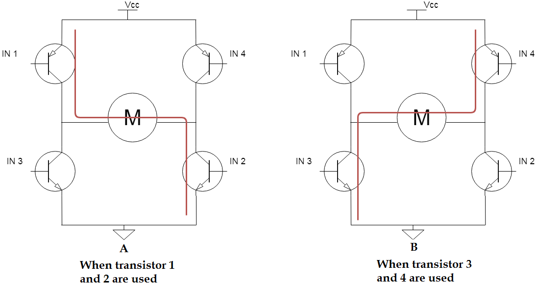
The main advantage of using an H-bridge is you only have to change the current direction to move the motor forward or backward rather than changing voltage polarity.
Two H-bridge diagrams are shown below, each with different current directions. In image A, turning the first and second transistor on causes the motor to turn clockwise. In image B, turning the third and fourth transistor on will cause it to turn counter-clockwise.
Here is the pinout of the IC
It requires two Vcc’s: 5V (Vcc1) for its internal driver operation and 12V (Vcc2) for the motor. The L293D can drive two motors at a time and for each motor, it has two input pins (A) and two output pins (Y).
At one input pin, we have to pass a HIGH digital signal and at other a LOW signal. These signals will then be amplified and given to the motor. Basically what we have done is, we have just applied a positive signal on one pin of the motor and LOW signal to another pin of the motor. This will tend to move the motor continuously in a particular direction at maximum speed. But for assigning speed, we will source PWM pulses from Arduino to enable the L293D’s pin.
Programming the Arduino and DC Motor
As far as programming is concerned, you need to set a motor to move in a particular direction and assign it a constant speed. The code is pretty straightforward.
digitalWrite(7,HIGH); //Move motor in clockwise direction
digitalWrite(6,LOW);
analogWrite(9,100); //speed
Upload the hex file of this code to the Arduino board and watch the motor rotate in the simulation.
The motor moving in the Proteus simulation.
Try to change the PWM’s duty cycle and observe a change in the speed of the motor.
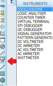
Next, you can set up PWM wave observation on the oscilloscope in Proteus. The oscilloscope can be found in the Instruments tab.
Locate the oscilloscope in the Instruments tab.
Connect the PWM pin to the oscilloscope.
Press the Play tab to observe PWM waves. The images below show PWM waves of 10%, 50%, and 90% duty-cycle.
Proteus is Great for Simulation
In this article, I showed you how to use Proteus for simulation. You installed the Arduino library in Proteus and performed two exercises: seven-segment LCD display and DC motor interfacing with Arduino.
I hope you enjoyed learning about Proteus. If you have any difficulty while using it, feel free to post about it in the comment section.