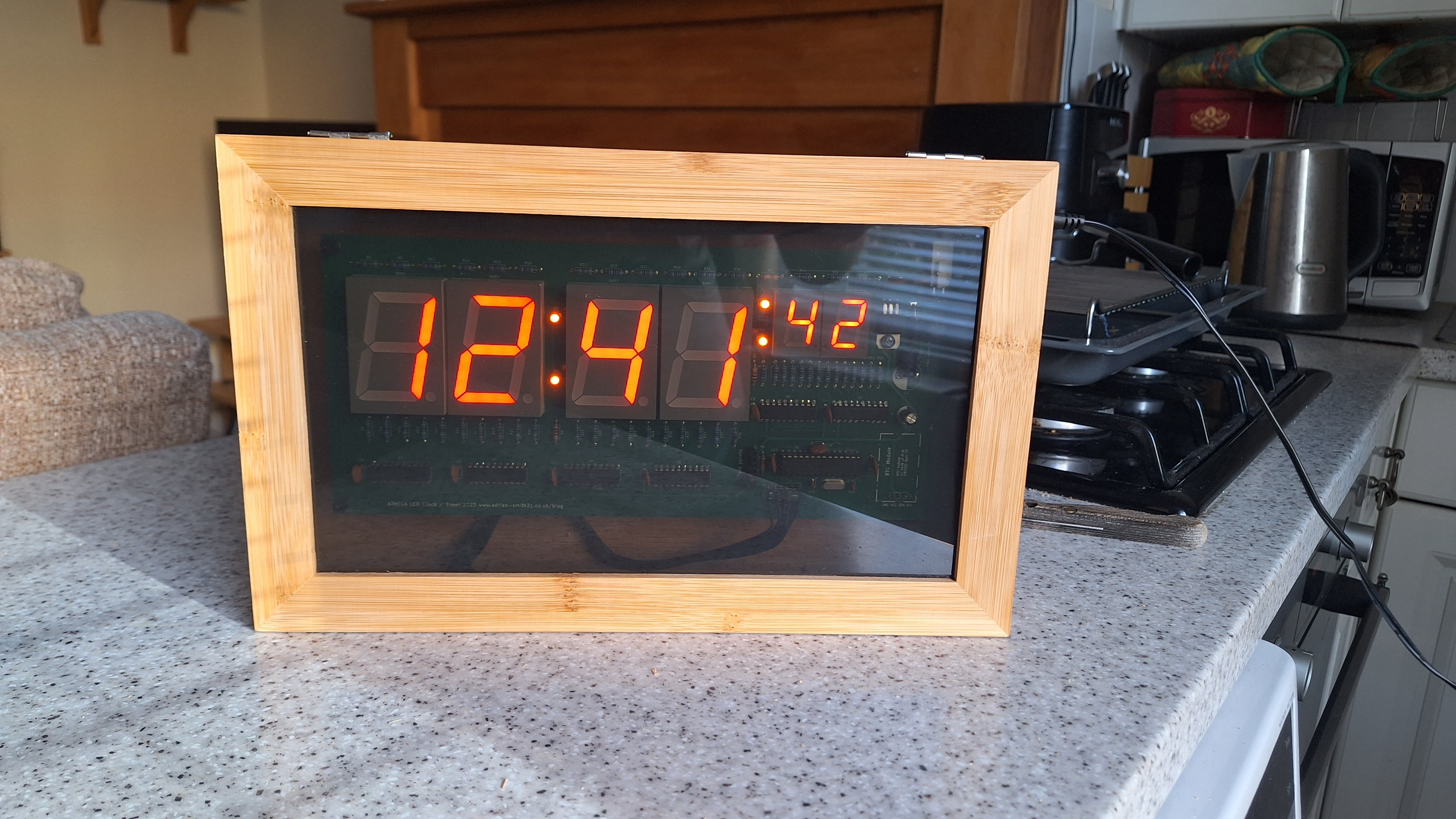
A large Arduino based LED clock using 1.8" high digits for the hours and minutes and 0.8" for the seconds. A DS3231 provides and accurate time source and the clock features dimming of the display at night and ability to set time to the second. It is powered from a 12V regulated power supply and has reverse polarity protection to prevent damage.
Intro
This idea came into being when I obtained some surplus 7 segment displays salvaged from old equipment which when tested lit up with a nice orange – red colour. They were originally from fruit machines so I decided to do something with them. As I haven’t made any projects for a while I made a large clock / timer which could be seen from a distance. I have made several clocks, one a bedside alarm clock which I still use nearly 5 years later and a couple for my living room. These were both using dot matrix modules instead of 7 segment displays. I decided to keep one and the other I took to work to use in the office.
The completed PCB mounted to a wooden base ready for installation into the case.
This third design is more traditional and uses 1.8″ high digits for the hours and minutes and 0.8″ high for the seconds rather than dot matrix display modules. It’s a large PCB measuring 270 x 110mm and I had trouble finding a suitable case for it. In the end I settled on a tea bag case with a clear glass lid. It has no branding or logos on it which made it ideal for a case once the internal compartments were removed. It was a bit too tall and I would have preferred something wide and less tall to match the size of the PCB but I wasn't able to find anything off the shelf reasonably priced.
The circuit
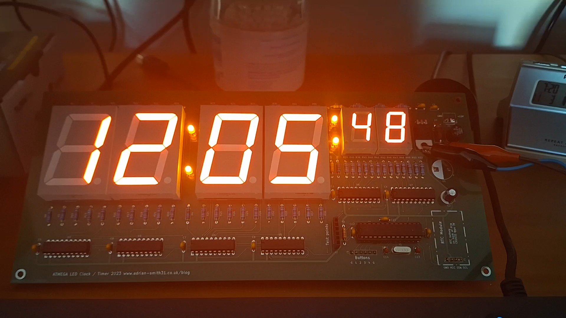
The clock uses 6 digits with a smaller pair of digits for the seconds which are connected to a chain of Texas Instruments TPIC6B595N power logic shift registers without multiplexing; one chip per digit. The reason behind this is the large LED displays have a forward voltage of around 6.3V and as such they need a 9-12V supply. I opted for a 12V regulated supply for the anodes which with multiplexing would result in high power dissipation through the TPIC6B595N controlling the segments. So I decided to use a non multiplexed design so that the shift registers are not dissipating too much.
An ATMEGA168P or ATMEGA328P controls the clock and the code was written with the Arduino IDE in C++. A DS3231 battery backed RTC provides the time base. A set of 3 buttons set the time through a simple menu with the ability to zero the seconds for synchronising with an accurate time source.
PWM on the shift registers Output Enable pin is used to control the brightness of the display and the colons also have two brightness control settings so they also dim with the main display.
Unfortunately there is no alarm feature on this clock but I am releasing the source code so you could add that feature if you wanted. A 4th button is provided but unused in this version of the code. This is simply because I had some 4 button PCB's made one of which I used for this project.
The PCB powered up from a bench PSU set to 12 volts.