In this tutorial, I am going to show you guys how to create a true LED fading effect using the 555 timer IC.
Wanted to generate a LED fading effect (fade-in and fade-out) for my upcoming video tutorial using the 555 timer IC.
I already have a video where I used LM358 Dual Operational Amplifier IC and another one with Arduino to generate the LED fading effect.
YouTube, is full of video showing how to generate the fading effect using 555 timer IC. However, none of them produce a true fading effect.
Some just fades-in but never fades-out. And there is literally no explanation of how they are generating the fading effect other than just showing how to assemble the components.
In this tutorial, I am going to show you guys how to create a true LED fading effect using the 555 timer IC. I will also explain how the circuit works and how changing components change the fading effect of the LEDs.
Components Required
For this tutorial you need:
1 x 555 Timer IC
1 x 47KΩ Resistor
1 x 220Ω Resistor
1 x BC548 NPN Transistor
1 x 33µF Capacitor, and
1 x Few Blue LEDs
Circuit Diagram
How The Circuit Works
* When Pin 2 of the IC detects voltage LESS than 1/3rd of the supply voltage, it turns ON the output on Pin 3.
* And, when Pin 6 detects voltage MORE than 2/3rds of the supply voltage, it turns OFF the output.
This is how the trigger pin (Pin2) and the threshold pin (Pin6) of the 555 timer IC sense voltages and controls the output at Pin 3.
* The Capacitor attached to the circuit will be in a discharged state immediately after firing up the circuit.
* So, the voltage at Pin 2 will be 0v which is less than 1/3rds of the supply voltage, this will turn ON the output on Pin 3.
* Since Pin 3 is looped back to Pin 2, it will start charging the Capacitor via the 47KΩ resistor.
* At the same time the base current of the transistor also increases causing the LED to slowly "fade-in".
* Once the voltage across the capacitor crosses 2/3rds of the supply voltage, Pin 6 turns OFF the output.
* This causes the capacitor to slowly discharge causing the base current to fall and hence the LED starts "fading-out".
* Once the voltage across the capacitor falls below 1/3rd of the supply voltage, Pin 2 turns ON the output, and the above cycle continues.
You can hook up a multimeter to the circuit to measure the charging and discharging of the capacitor.
Breadboard Demo
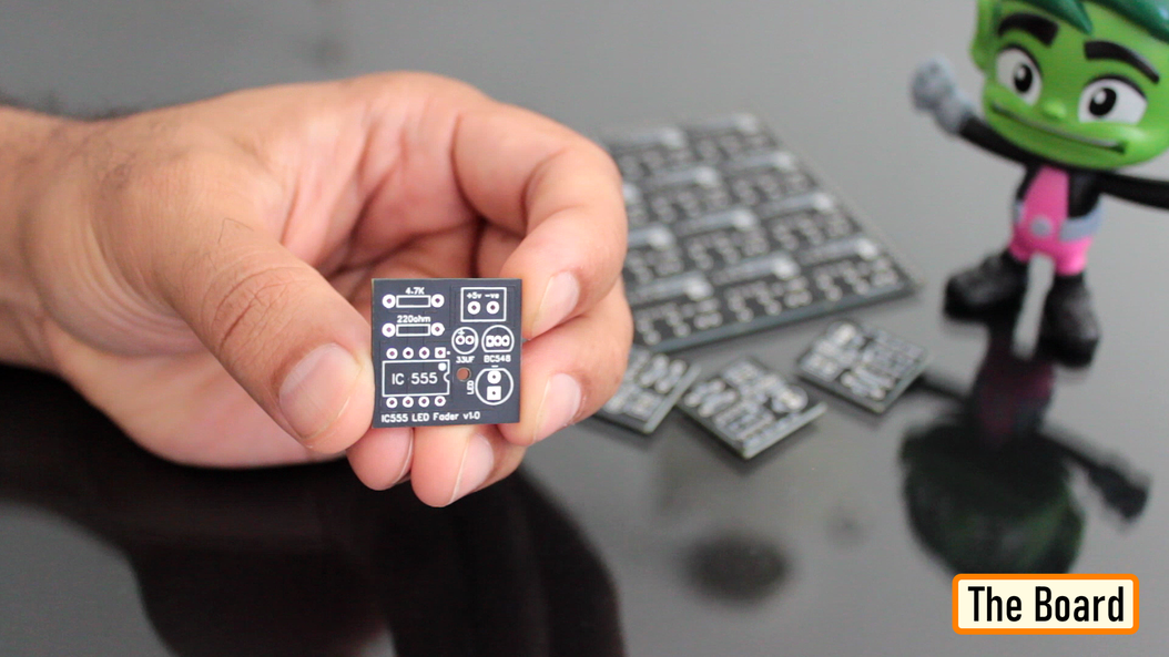
The Board
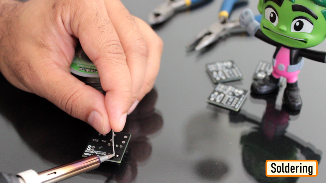
Soldering
Let me quickly show you guys how to assemble the components to this custom made board.
Let's start by soldering the IC Base to the board.
Then let's solder the two resistors to the board. Next, lets solder the capacitor followed by the transistor to the board. Then, lets solder a blue LED to the board.
Once done, let's insert the 555 timer IC to the IC base.
To conclude the setup, I soldered 2 x Female pin headers to the board. You can either solder a pair of female pin-header or male pin-header or solder a pair of wires directly to the board to power this module.
Demo
Cool, so this is how my module finally looks like.
You can install female pin-headers in-place of the LED or Capacitor if you plan to use this as a development/testing board instead of a module.
Thanks