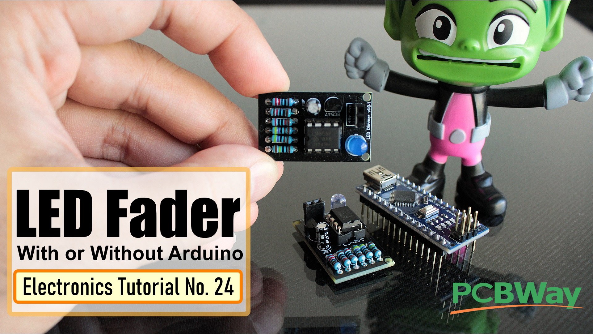
How to fade a LED with or without an Arduino automatically or manually using a potentiometer.
Have an awesome project in mind using some LEDs. In that project I will be using some LED Fading Effect and few LED Chaser Circuits. But before jumping onto that, I thought I should create a short tutorial and how you guys how to fade a LED with or without an Arduino automatically or manually using a potentiometer.
Video: https://youtu.be/IIUsdICycOw
PCBway: only $5 for 10 PCBs from https://www.pcbway.com/?from=CZcouple
Lets first create the fader circuit without an Arduino. The base of this circuit is an operational amplifier IC named LM358. In this circuit, initially, the LED slowly glows with increasing brightness & after reaching its maximum brightness, the LED slowly dims its brightness and the process continues.
Automatic Fading
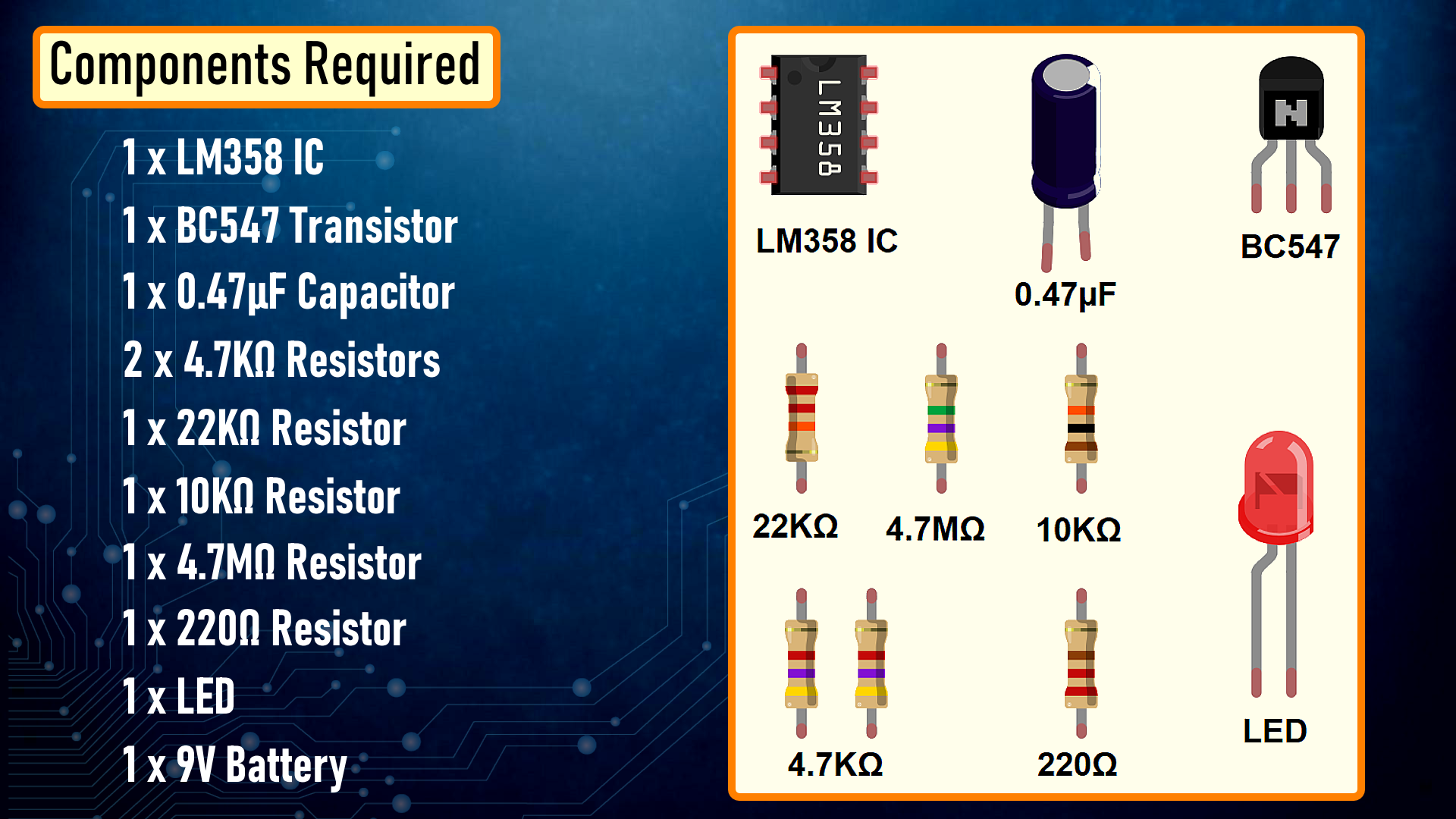
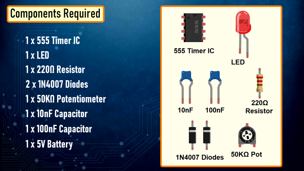
Components Required
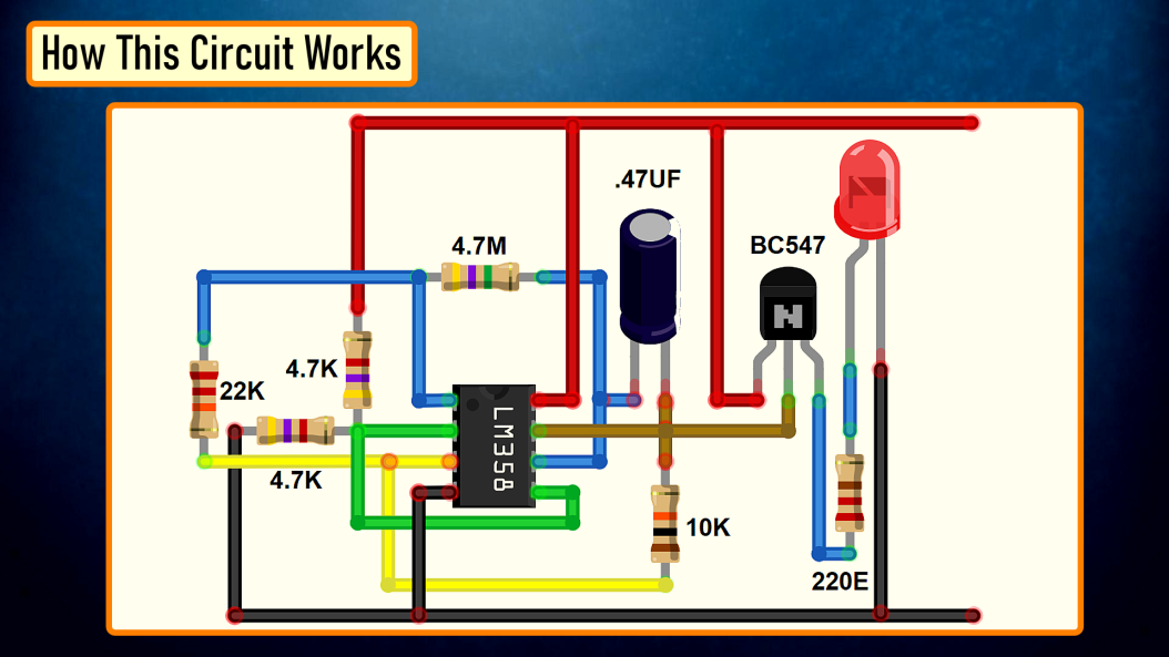
How This Circuit Works
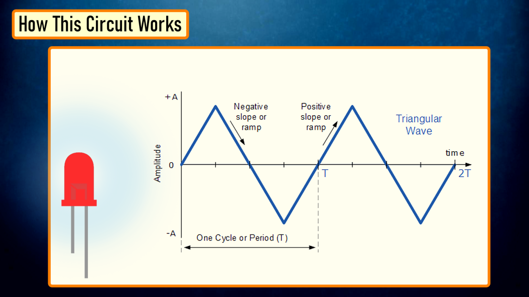
To get the fading effect we need to generate a series of triangular waves.
Because of the triangular waves, the LED starts glowing slowly and then slowly dims off and the cycle continues.
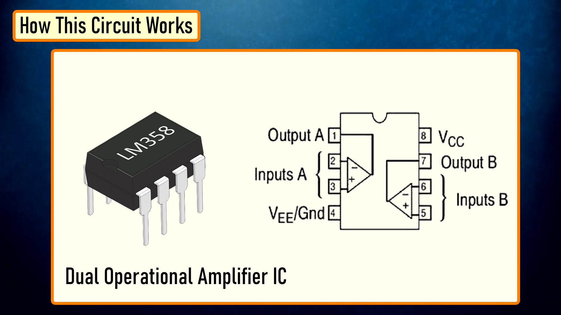
This setup is done using the LM358 IC. LM358 is a dual operational amplifier (Op-Amp) IC, integrated with two op-amps powered by a common power supply. Pins 1, 2, and 3 are one op-amp channel, and pins 5, 6, and 7 are the 2nd op-amp channel.
As the capacitor charges and discharges the state of the PIN 3 switches from high to low and based on that the PIN 2 of the op-amp obtains the desire output. If you want to know more about this IC, please check out my "Tutorial No 21 : DIY - IR Module" : https://youtu.be/_M8FQIPi1qk.
So, basically the op-amp here is used for voltage level detection. In this circuit, we are applying a voltage on positive pin (PIN-3) and the voltage to be detected is applied at negative pin (PIN-2).
The transistor acts as a signal amplifier. You will need this if you are attaching a cluster of LEDs however for just 1 LED you can simply remove it.
The Board
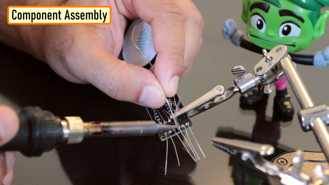
Component Assembly
Now, lets solder all the components to the board. Lets first solder all the resistances to the board. Then lets solder the transistor followed by the capacitor to the board. After that lets solder the LED and the female pin header. To conclude the setup, lets solder the IC base and then install the IC into it.
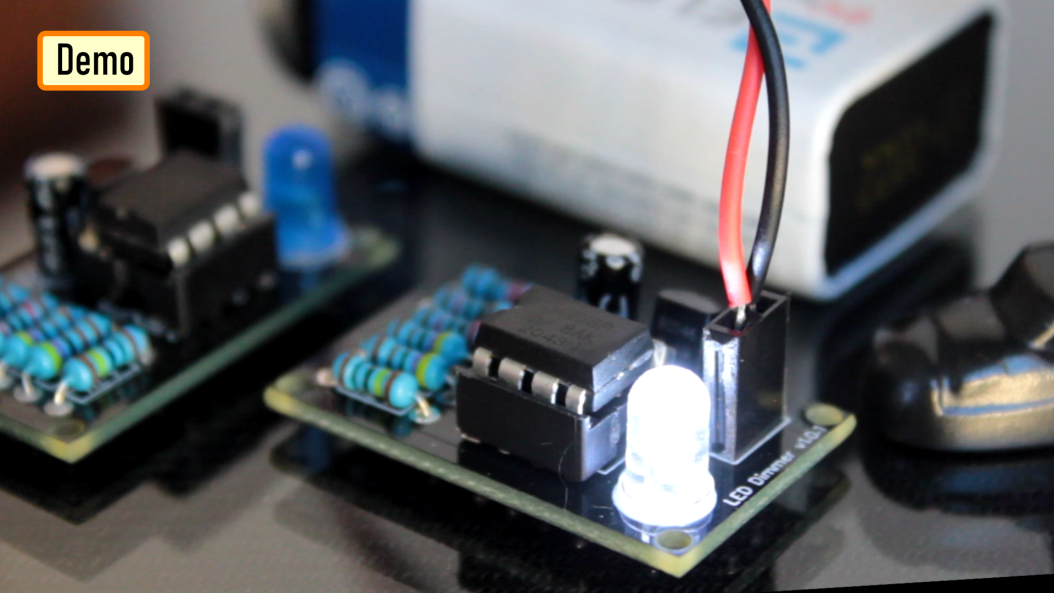
Demo
So, this is how it looks like.
Good thing about LEDs is that they can be easily controlled as compared to the traditional light bulbs. Which means you can easily change their intensity based on your need. Just by making a slight modification to this circuit you can change the brightness of a LED Lamp when someone walks in or out of a room.
Manual Fading Using PWM
Now, if you want to get the same dimming effect but want to manually control the intensity, you will have to find a way to modulate the pulse sent to the LED or group of LEDs using a potentiometer. I am going to do this by generating PWM Signals.
What is PWM?
Pulse Width Modulation, or PWM, is a technique for getting analog results with digital means.
PWM value varies from 0 to 255. The bigger the value of PWM, the brighter the LED is and vice versa.
- If PWM = 0, it is same as GND, so the LED will be OFF
- If PWM = 255, it is same as VCC, so the LED will be fully ON
To get varying analog values, you change, or modulate, that pulse-width. If you repeat this on-off pattern fast enough with an LED, the result is as if the signal is a steady voltage between 0 and 5v controlling the brightness of the LED.
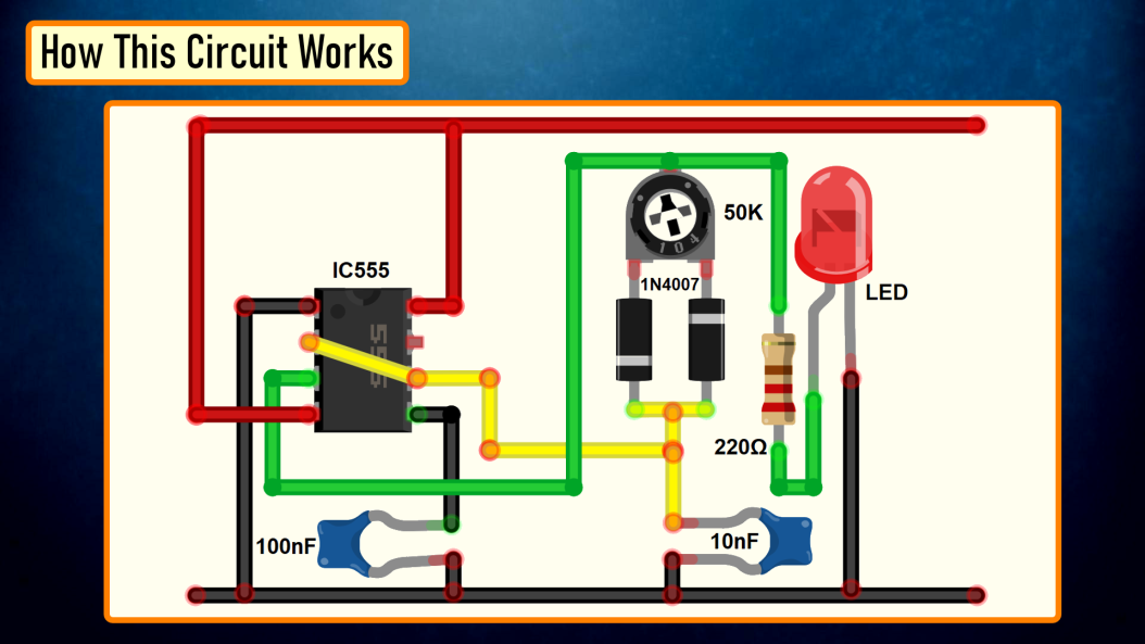
In this setup, we are going to use the 555 Timer IC in Astable mode (A free-running multivibrator that has NO stable states but switches continuously between two states this action produces a train of square wave pulses at a fixed known frequency) to generate the PWM Signals. 555 Timer IC will vary the voltage delivered to the LEDs to achieve the Dimming effect of the LED.
Components Required
How This Circuit Works
Based on the charging and discharging timings of the Capacitor, a PWM Signal is generated at PIN 3 (OUT PIN) of the 555 Timer IC. The output is then sent to the LED to produce the dimming effect.
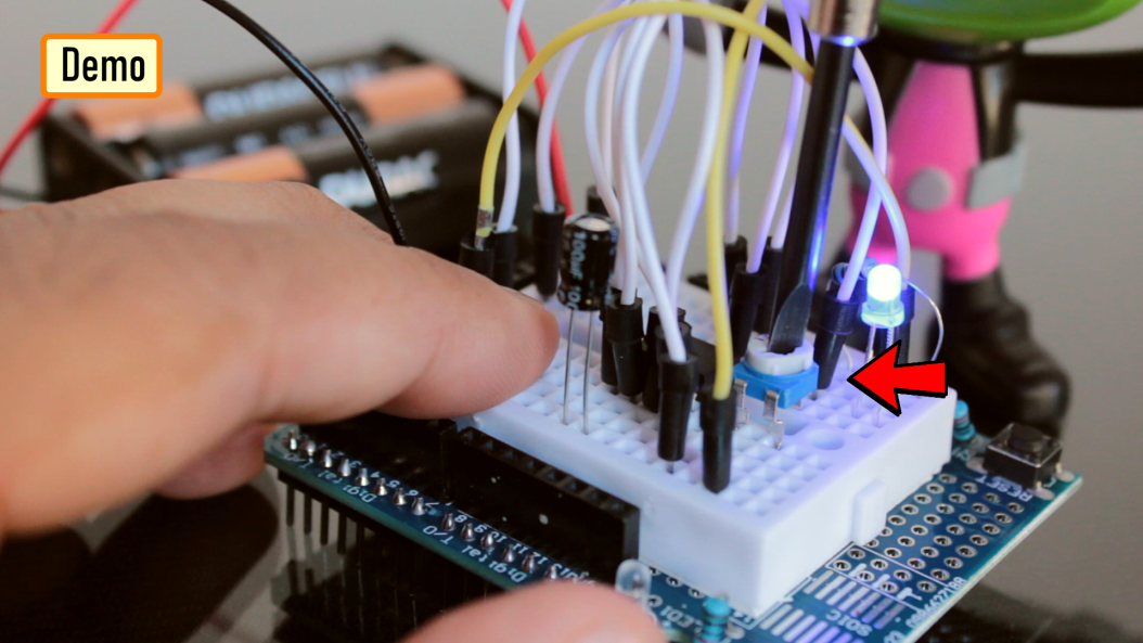
Demo
So, this is how it looks like.
By rotating the knob of the 10K Pot we can adjust the brightness of the connected LED.
With Arduino
Now, lets repeat these setups using an Arduino. The beauty of Arduino is that it has 6 digital pins that can be used as PWM outputs (3, 5, 6, 9, 10, and 11). PWM signals are sent using the analogWrite() function by passing a value between 0 - 255.
- analogWrite(255) requests a 100% duty cycle (always on),and
- analogWrite(127) is a 50% duty cycle (on half the time), and so on.
Components Required
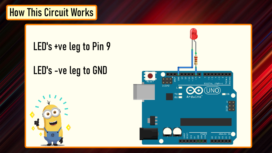
Automatic Fading
Connect the positive leg of your LED to the digital output PIN9 of your Arduino through a 220Ω resistor. Connect the negative leg directly to the GND. That it, that's how simple it is.
The Code
After declaring PIN 9 as LedPin, and setting up the pinMode in the setup() section, we are going to loop through and dim the LED in the loop section.
By gradually increasing the PWM value from 0 to 255, and then back to 0 we can get the fading effect. In this sketch, the PWM value is set using a variable called 'brightness'. Each time in the loop, it increases by the value of the variable 'fadeAmount'.
If brightness is at either extreme of its value (either 0 or 255), then 'fadeAmount' is changed to its negative. So, if the fadeAmount is 5, then it is set to -5 and if it is -5, then it is set to 5. The next time through the loop, this change causes brightness to change its direction. A delay is added to control the speed of the fading effect.
Demo
So, this is how it looks like.
Manual Fading
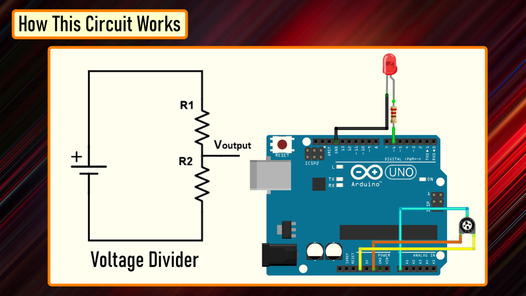
Connect the positive leg of your LED to the digital output PIN6 of your Arduino through a 220Ω resistor. Connect the negative leg directly to the GND. Connect the left (or right) pin of the 50KΩ PoT to VCC and then connect the right (or left) pin of the PoT to the GND. Now, connect the 'data' pin of your potentiometer to the Analog PIN 'A0' of the Arduino.
In this circuit, the potentiometer is working as a voltage divider. One of the outer pins is connected to the GND, the other to Vcc and the middle pin is the voltage output. The wiper position in this setup determines the output voltage.
Now, lets have a look at the code.
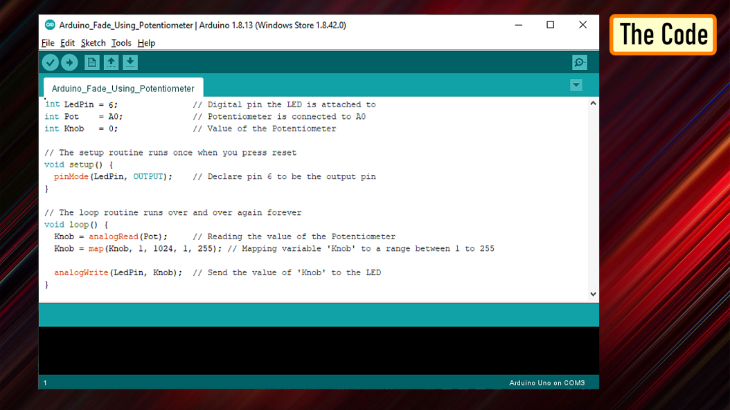
The Code
Based on my setup, I set the LedPin as 6 and Potentiometer pin Pot as A0. Another variable 'Knob' is used to read and store the value of the potentiometer.
pinMode of the LedPin is set to OUTPUT and we don't need to do anything for the PoT as its default value is already set as input.
In the 'loop()' section I am first reading the value of the PoT using the 'analogRead()' function and then mapping its value between 1 to 255. A potentiometer intakes a value between 1 and 1024, but in our setup it has to be between 1 to 255. The 'map()' function divides the value read from the potentiometer into equal intervals of 1/255, which is then sent to the LED using the 'analogWrite()' function.
Demo
So, this is how it looks like.
Thanks