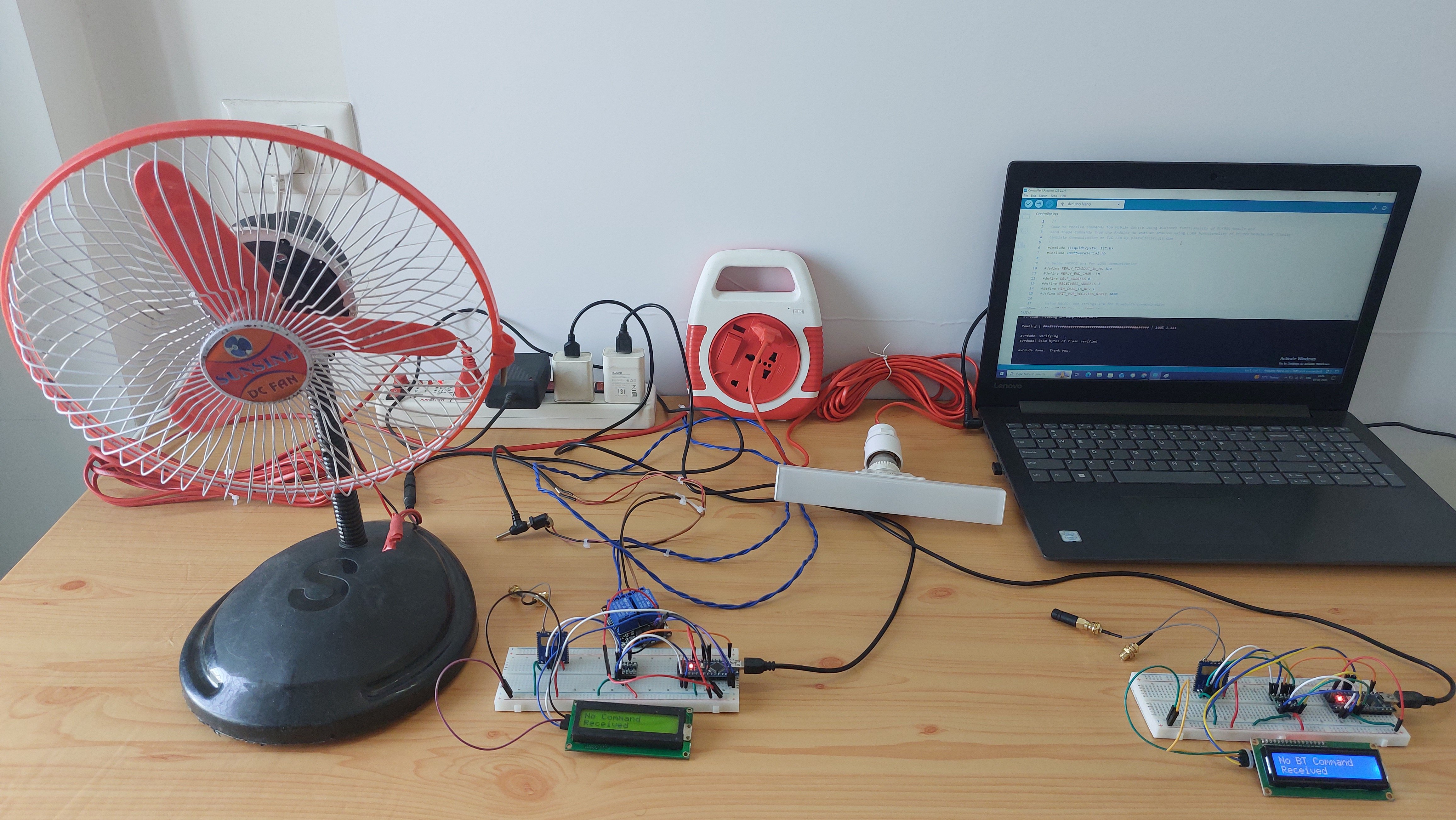
Build a long-range wireless appliance controller using Arduino Nano and the Reyax RYLR999. A smartphone sends commands over BLE, while LoRa carries them to a remote Arduino that switches a bulb or fan through relays—without requiring Wi-Fi or internet connectivity.
Controlling an appliance from a smartphone is fairly easy when everything is connected to the same Wi-Fi network. The problem starts when the device is somewhere outside the range of your local network.
For this project, I wanted to try a different approach: use Bluetooth for the nearby smartphone connection and LoRa for the long-distance link.
The result is a two-node wireless control system built around Arduino Nano and Reyax RYLR999 modules. A phone sends a command to the first node over Bluetooth Low Energy (BLE). The Arduino passes that command to the RYLR999, which sends it over LoRa to a second node. The receiving Arduino then operates a relay to switch a bulb or fan.
The system doesn't need Wi-Fi or an internet connection. That makes the same basic idea useful for remote lighting, agricultural equipment, pumps, or other installations where network connectivity isn't readily available.
How the System Is Arranged
There are two separate units in the project: a controller and a target.
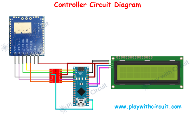
The controller node is placed near the person operating the system. It contains an Arduino Nano, RYLR999 module, voltage level shifter, and an I2C LCD. The smartphone connects to the RYLR999 through BLE using the LightBlue application.
When a command is received, the Arduino processes it and sends the required data through the LoRa interface of the module.
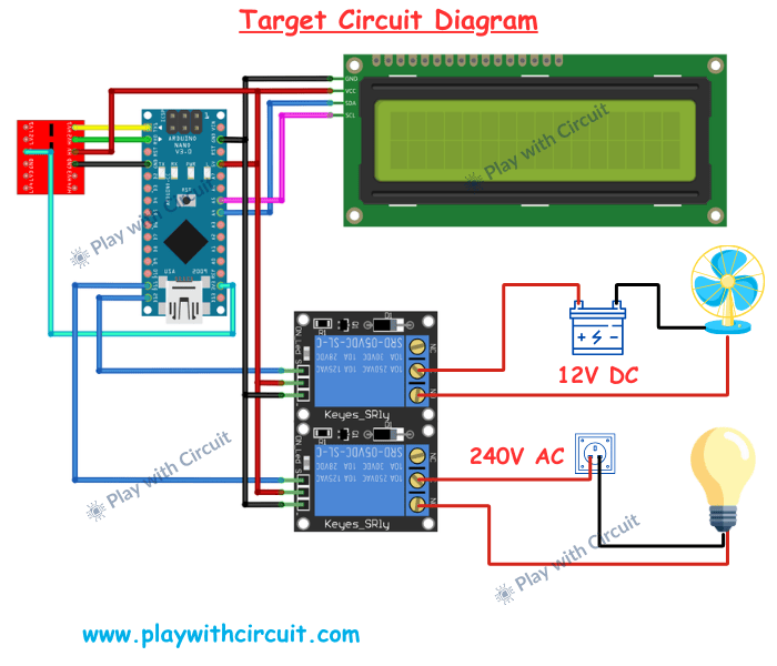
The target node is located near the appliances. It contains another Arduino Nano and RYLR999 module, along with the relay module and LCD. The second RYLR999 receives the LoRa transmission and passes the command to the Arduino. The Arduino then decides which relay needs to be activated.
After carrying out the command, the target node sends a confirmation back through LoRa. This gives the controller a simple way of knowing whether the remote operation was completed.
The overall communication path is:
Smartphone → BLE → Controller Arduino → LoRa → Target Arduino → Relay → Appliance
The response travels in the opposite direction.
Hardware Required
The build uses two Arduino Nano boards and two Reyax RYLR999 modules.
You'll also need two bidirectional voltage level shifters, two 16×2 I2C LCD displays, and a two-channel relay module. For testing the outputs, I used a 12V DC fan and a 240V AC bulb.
The remaining parts are jumper wires and suitable power supplies for the Arduino and fan.
The level shifters are particularly important because the Arduino Nano uses 5V logic while the RYLR999 communication interface uses 3.3V logic.
Connections
The RYLR999 has separate UART connections for its BLE and LoRa interfaces.
Its main pins used here are VDD, GND, RST, TXD_BLE, RXD_BLE, TXD_LoRa, and RXD_LoRa.
The controller Arduino communicates with the LoRa interface through the Nano's hardware serial pins. The Arduino's RX pin receives data from TXD_LoRa, while its TX pin sends data toward RXD_LoRa. Both connections pass through the voltage level shifter.
Since the Nano has only one hardware serial port, the BLE interface is handled using SoftwareSerial. Digital pin 2 is used as the BLE transmit connection and digital pin 3 as the BLE receive connection. These signals also pass through the level shifter.
The module's VDD and GND are connected to the appropriate supply and common ground.
The 16×2 LCD uses an I2C interface, so only the power and two communication lines are required.
Connect VCC and GND to the Arduino's corresponding supply pins. The LCD's SDA line connects to A4, while SCL connects to A5 on the Arduino Nano.
For the LCD module used in this project, the I2C address is 0x27. The address jumpers on the rear of the LCD backpack should remain open when using this address.
The display is mainly there to make the communication process visible during testing. It can show initialization messages, received commands, transmission information, and responses from the remote node.
Target Node Connections
The target circuit follows the same basic LoRa communication arrangement, but BLE is not required on this side.
The second RYLR999 communicates with the Arduino Nano through its LoRa UART interface. Again, a bidirectional level shifter is placed between the 5V Arduino and 3.3V module signals.
The major addition here is the relay module.
The first relay input is connected to D11 and is used for the bulb. The second relay input is connected to D12 and controls the fan.
The relay module is powered from the Arduino supply, with VCC connected to 5V and GND connected to common ground.
The target LCD is connected to the Arduino's I2C pins in the same way as the controller LCD.
Connecting the Appliances
The relay provides the interface between the Arduino's low-voltage control circuit and the actual loads.
For the DC fan, the relay is placed in series with the 12V supply going to the fan. When the Arduino activates the second relay channel, the relay contacts close and the fan receives power.
The AC bulb is connected through the first relay channel. The live conductor from the AC supply is switched through the relay's common and normally-open contacts.
Mains wiring should only be carried out by someone who understands the relevant electrical safety requirements. Disconnect the AC supply completely before making or changing connections.
Command Format
The commands used by the controller are deliberately simple.
From the smartphone, the following commands can be sent:
*L1# – Turn the bulb ON
*L0# – Turn the bulb OFF
*F1# – Turn the fan ON
*F0# – Turn the fan OFF
The controller Arduino reads the BLE data and identifies the requested operation before forwarding the corresponding command over LoRa.
At the target side, the Arduino interprets the received command and operates the appropriate relay.
Once the operation is completed, the target sends a DONE response back to the controller.
The commands shown above represent the application-level payload. The RYLR999 itself uses its own AT-command format for LoRa transmission, so the actual transmitted data also includes information required by the module, such as the destination address and payload length.
Testing the Build
Final Thoughts
This project started with a fairly simple requirement: control an appliance remotely without depending on Wi-Fi.
Using the RYLR999 makes the architecture interesting because BLE and LoRa can be used together. BLE handles the convenient smartphone interface, while LoRa provides the long-distance connection between the two Arduino nodes.
The result is a relatively simple platform that can be extended well beyond the bulb-and-fan demonstration.
I've documented the complete circuit details, source code, configuration, and additional troubleshooting information in the original Play with Circuit tutorial:
https://playwithcircuit.com/long-range-appliance-control-from-smartphone-using-arduino/
That version can be used as the detailed reference while this Maker Pro project focuses on the architecture and practical implementation.