Tree poaching detector using Arduino UNO, LoRa Module with PIR sensor, Vibration sensor, and Sound sensor
A tree poaching detector using a PIR motion sensor ,Vibration sensor and Sound sensor integrated into Arduino UNO to tree cutting activity.
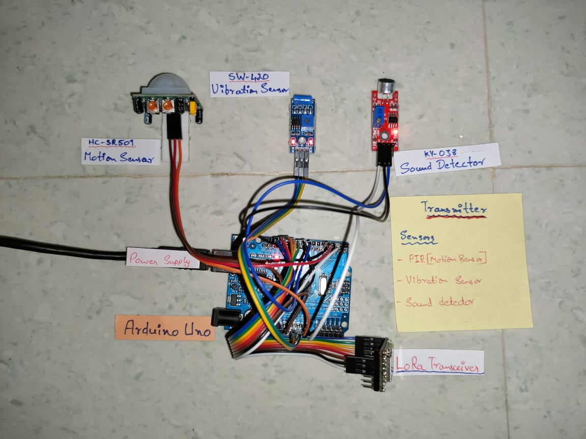
Transmitter Module
This module has Arduino UNO which is connected with a PIR sensor, Vibration sensor, Sound sensor, and a LoRa Transmitter to transmit all the sensor's data to the receiver module.
Arduino UNO and LoRa Connections
Arduino UNO (Pins) | Lora SX1278 |
|---|
9 | RST |
2 | DIO0 |
12 | MISO |
11 | MOSI |
10 | NSS |
13 | SCK |
GND | GND |
3.3 V | Vin |
Transmitter Module circuit Diagram
Arduino UNO and PIR Sensor Connections
Arduino UNO (Pins) | PIR Sensor |
|---|
5 | OUT |
5V | VCC |
GND | GND |
Arduino UNO and Vibration Sensor Connections
Arduino UNO | SW-420 Vibration sensor |
|---|
8 | OUT |
5v | VCC |
Gnd | Gnd |
Arduino UNO and Sound sensor Connections
Arduino UNO | Sound Sensor |
|---|
A0 | AOUT |
5v | VIN |
GND | GND |
Transmitter code
#include <SPI.h>
#include <LoRa.h>
#define PIR_PIN 5   // Motion sensor pin
#define V_PIN 8     //Vibration sesor pin

//***********************************LoRa pins ***********************************//
#define ss 10         //NSS pin
#define rst 9         //Reset pin
#define dio0 2        //Interrupt pin

int  SOUND_VALUE = 0;
int  SOUND_STATUS, MOTION_STATUS, Vibration_STATUS;     //Sensor status variables
int M_code, V_code, S_code, Alert_code;                 //Code for each sensor
int DEVICE_ID = 1234;

void setup()
{
  pinMode(PIR_PIN, INPUT);      //Set Motion sensor as input
  pinMode(V_PIN, INPUT);        //Set Vibration sensor as input
  digitalWrite(PIR_PIN, LOW);
  LoRa.setPins(ss, rst, dio0);    //Set LoRa pins
  Serial.begin(9600);
  Serial.println("LoRa Transmitter");
  if (!LoRa.begin(433E6))         //Initialize LoRa with frequency 433 MHz
  {
    Serial.println("Starting LoRa failed!");
    while (1);
  }

  LoRa.setSpreadingFactor(7);         //12 for max range
  LoRa.setSignalBandwidth(62.5E3);    //Bandwidth to 63.5KHz
  Serial.println("TREE POACHING DETECTOR");

  LoRa.beginPacket();
  LoRa.print("TREE POACHING DETECTOR");       //Send
  LoRa.endPacket();
  digitalWrite(PIR_PIN, LOW);
}

void loop()
{
  if (digitalRead(PIR_PIN) == HIGH)
  {
    Serial.println("MOTION DETECTED");
    MOTION_STATUS = 1;
    M_code = 11;
  }

  else {
    M_code = 0;
  }

  if (digitalRead(V_PIN) == HIGH)
  {
    Serial.println("VIBRATION DETECTED");
    Vibration_STATUS = 1;
    V_code = 22;
  }

  else {
    V_code = 0;
  }

  SOUND_VALUE = analogRead (A0);
  if (SOUND_VALUE > 660)
  {
    Serial.println (SOUND_VALUE, DEC);
    Serial.println ("SOUND DETECTED");
    SOUND_STATUS = 1;
    S_code = 33;
  }

  else {
    S_code = 0;
  }

  if (SOUND_STATUS == 1 && MOTION_STATUS == 1 && Vibration_STATUS == 1) {
    Serial.println ("INTRUDER ALERT!!!");
    Alert_code = 44;
    SOUND_STATUS = 0;
    Vibration_STATUS = 0;
    MOTION_STATUS = 0;
  }
  else {
    Alert_code = 0;
  }
  LoRa.beginPacket();
  LoRa.print(DEVICE_ID);
  LoRa.print("|");
  LoRa.print(M_code);
  LoRa.print("|");
  LoRa.print(V_code);
  LoRa.print("|");
  LoRa.print(S_code);
  LoRa.print("|");
  LoRa.print(Alert_code);
  LoRa.print("|");
  LoRa.endPacket();
 delay(100);
}
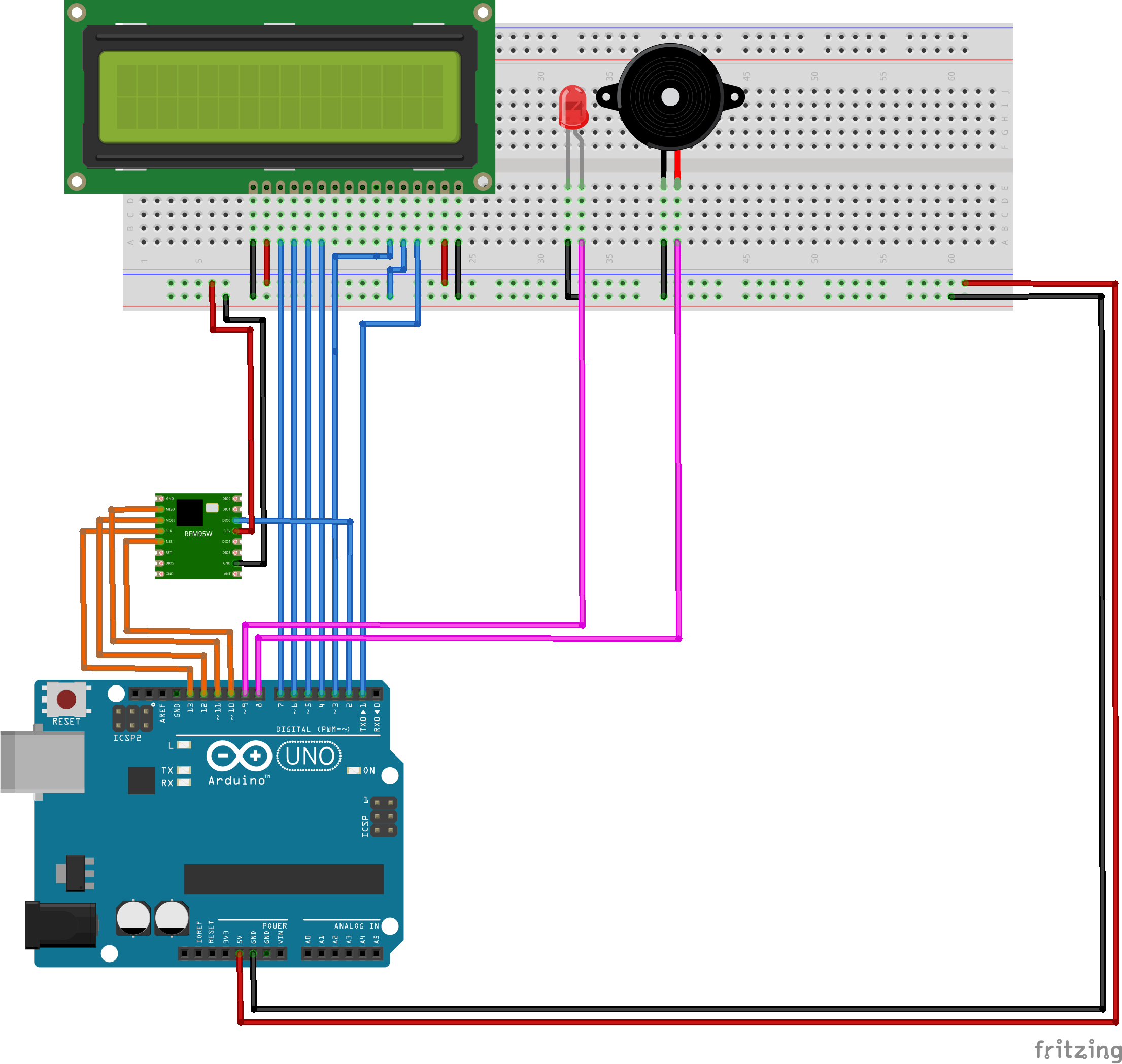
Receiver Module
The receiver module has Arduino uno module which is connected with 16x2 LCD display to show the sensor status received from the transmitter module , and a LED and Buzzer is connected for indication of tree poaching activity.
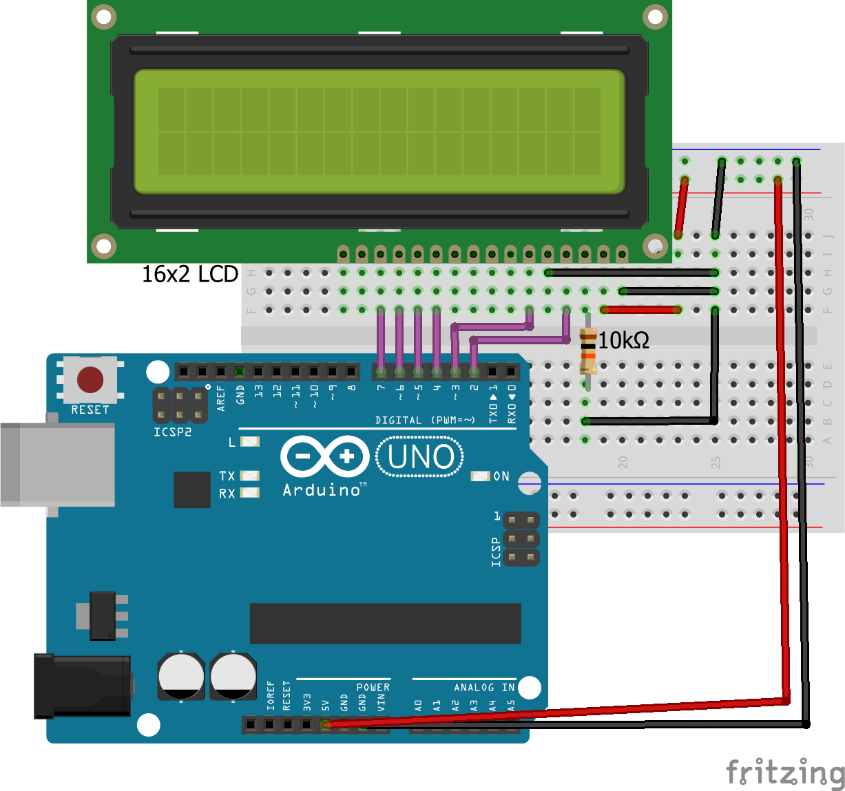
Arduino Uno and 16x2 LCD connections
Arduino UNO | 16x2 LCD |
|---|
8 | RS |
3 | EN |
4 | D4 |
5 | D5 |
6 | D6 |
7 | D7 |
5v | VDD |
Gnd | VSS |
Arduino Uno and LoRa Module
Arduino UNO (Pins) | Lora SX1278 |
|---|
9 | RST | 2 | DIO0 | 12 | MISO | 11 | MOSI | 10 | NSS | 13 | SCK | GND | GND | 3.3 V | Vin |
|
|---|
And finally Buzzer is connected to Pin 1 in Arduino Uno
Receiver Code
#include <LiquidCrystal.h>  //Library for liquid crystal display
#include <SPI.h>            //Library for SPI protocol
#include <LoRa.h>           //Library for LoRa
#define RS 8
#define EN 3
#define D4 4
#define D5 5
#define D6 6
#define D7 7      //LCD pins
#define Buzzer 1  //Buzzer pin

/**************************LoRa Pins *************************/
#define ss 10     //Slave select pin
#define rst 9     //Reset pin
#define dio0 2    //Interrupt pin
LiquidCrystal lcd(RS, EN, D4, D5, D6, D7); //Let the library know how we have connected the LCD pins
int i = 0;
String MOTION, VIBRATION, SOUND, ALERT_STATUS, DEVICE_ID;


/**************************ALERT FUNCTION *************************/
void alert()
{
  lcd.clear();
  lcd.setCursor (0, 0);
  lcd.print ("INTRUDER ALERT!!!");
  lcd.setCursor (0, 1);
  lcd.print ("DEVICE ID=" + DEVICE_ID);
  while (1)
    digitalWrite(Buzzer, HIGH);
  delay(100);
  digitalWrite(Buzzer, LOW);
}


/************************** SETUP *************************/
void setup()
{
  Serial.begin(9600);
  lcd.begin(16, 2);               //Begin 16x2 LCD
  lcd.setCursor (0, 0);           //sets the cursor at row 0 column 0
  lcd.print("LORA RECEIVER");
  delay(1000);
  lcd.setCursor (1, 1);           //sets the cursor at row 1 column 1
  lcd.print ("INITIALIZING");
  delay(1000);
  lcd.clear();
  pinMode(Buzzer, OUTPUT);          //Set Buzzer as output
  LoRa.setPins(ss, rst, dio0);    //Set LoRa pins
  if (!LoRa.begin(433E6))         //Begin LoRa with Frequency 433MHz
  {
    lcd.setCursor (0, 0);
    lcd.print("LORA FAILED");
    Serial.print("lora failed");
    while (1);
  }
  LoRa.setSpreadingFactor(7);       //Set spreading factor to 7
  LoRa.setSignalBandwidth(62.5E3);  //Set LoRa Operating bandwidth to 62.5GHz
  Serial.print("lora started");

  digitalWrite(Buzzer, HIGH);       // After LoRa initializaton buzzer give alert
  delay(500);
  digitalWrite(Buzzer, LOW);
}

void loop ()
{
  lcd.setCursor (1, 0);
  lcd.print ("SENSOR STATUS");
  lcd.setCursor (1, 1);
  lcd.print ("M=");             //'M' Stands for Motion
  lcd.setCursor (5, 1);
  lcd.print ("V=");             //'V' Stands for Vibration
  lcd.setCursor (9, 1);
  lcd.print ("S=");             //'S' Stands for Sound

  int packetSize = LoRa.parsePacket();
  if (packetSize == 0)return;

  while (LoRa.available()) {
    DEVICE_ID = LoRa.readStringUntil('|');
    MOTION = LoRa.readStringUntil('|');
    VIBRATION = LoRa.readStringUntil('|');
    SOUND = LoRa.readStringUntil('|');
    ALERT_STATUS = LoRa.readStringUntil('|');
  }
  Serial.print(DEVICE_ID);
  Serial.println(MOTION);
  Serial.println(VIBRATION);
  Serial.println(SOUND);

  if (ALERT_STATUS == "44")      //'44' is a code to alert
  {
    alert();
  }
  if (MOTION == "11")          //'11' is a code to Motion status
  {
    lcd.setCursor (3, 1);
    lcd.print ("Y");
  }
  if (VIBRATION == "22")       //'22' is a code to Vibration status
  {
    lcd.setCursor (7, 1);
    lcd.print ("Y");
  }
  if (SOUND == "33")           //'33' is a code to Sound sensor status
  {
    lcd.setCursor (11, 1);
    lcd.print ("Y");
    alert();            // calling alert function
  }
}
Receiver Module Circuit Diagram
Receiver Module circuit diagram
Demo Video