In this article, you will learn how to control the Arduino using gestures through the Wekinator platform.
In this article, part 8 of a larger machine learning series, you are going to learn how to control the Arduino using gestures through the Wekinator platform. We will give the input to Wekinator from the webcam using the processing code, and after training Wekinator, the other processing code will take the output from the processing and give it to the Arduino, where the buzzers will play different noises according to the gesture.ur project.
Catch up on the rest of the Wekinator Machine Learning series here:
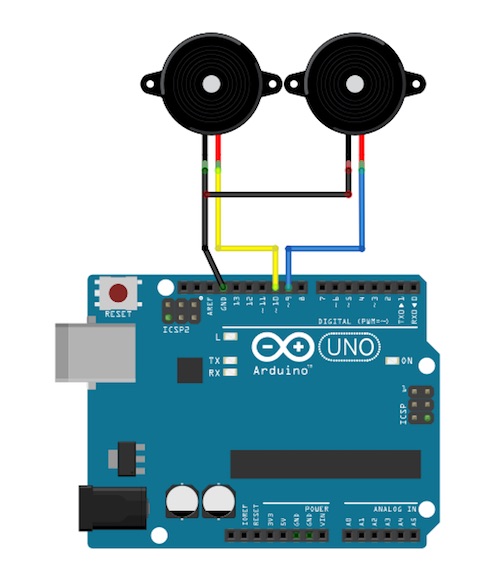
Circuit Diagram
Connect the positive of one of the buzzer to pin 9 of Arduino and the positive of the other buzzer to pin 10 of Arduino. Then connect the negative of both the buzzers to the ground of Arduino.section of your project.
How to Run the Code
First of all, paste the code given for the Arduino at the end of this post in the Arduino IDE and upload the code.
Then you will need to download the sketch from the examples page of Wekinator.
Download source code to process a simple 10x10 color grid. Unzip it and run the code in processing. This program will use your laptop’s webcam, and depending on what you are doing in front of the camera, it will give the input to Wekinator.
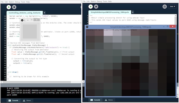
You will need another sketch for the output from Wekinator. The code for that sketch at in the end of this post. Paste that into processing and run the sketch. This sketch will take the output from the Wekinator and will send it to the Arduino, where the buzzers will play different sounds.
Both the processing windows should look like shown below.
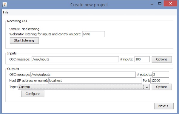
Now open the Wekinator and make the settings as shown in the below figure. Set the inputs to 100 and the outputs to 2. Set the type to “custom” and click on “configure”.
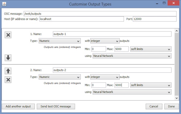
When you click on “configure”, a new window will open up like the one shown below. Change the settings as shown in the below figure.
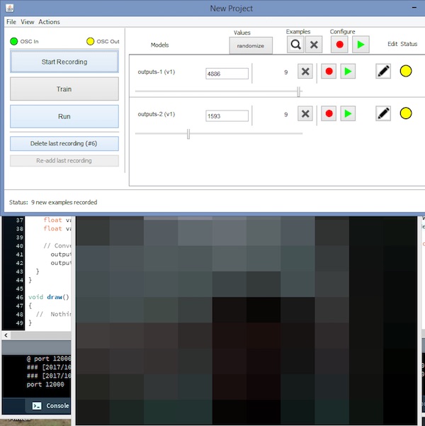
Now step aside from the webcam and click on “randomize”. Start the recording for half a second.
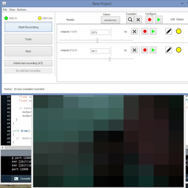
Now show your right hand at the right side of the webcam and click on “randomize”. Then start the recording for half a second.
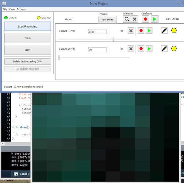
Now show your left hand at the left side of the webcam and click on “randomize”. Then start the recording for half a second.
After that, click “Train”, then “Run”. Now the Arduino will play the sounds according to the gesture you are showing in front of the webcam.
Processing Code (Output From Wekinator)
import vsync.*; // Importing the library that will help us in sending and receiving the values from the Arduino
import processing.serial.*;  // Importing the serial library

// Below libraries will connect and send, receive the values from wekinator
import oscP5.*;
import netP5.*;

// Creating the instances
OscP5 oscP5;
NetAddress dest;
ValueSender sender;

// These variables will be syncronized with the Arduino and they should be same on the Arduino side.
public int output;
public int output1;


void setup()
{
  // Starting the serial communication, the baudrate and the com port should be same as on the Arduino side.
  Serial serial = new Serial(this, "COM10", 19200);
  sender = new ValueSender(this, serial);

  // Synchronizing the variables as on the Arduino side. The order should be same.
  sender.observe("output");
  sender.observe("output1");

  // Starting the communication with wekinator. listen on port 12000, return messages on port 6448
  oscP5 = new OscP5(this, 12000);
  dest = new NetAddress("127.0.0.1", 6448);
}

// Recieve OSC messages from Wekinator
void oscEvent(OscMessage theOscMessage) {
  if (theOscMessage.checkAddrPattern("/wek/outputs") == true) {
    // Receiving the output from wekinator
    float value = theOscMessage.get(0).floatValue(); // First output
    float val = theOscMessage.get(1).floatValue();  // Second output

    // Converting the output to int type
      output = int(value);
      output1 = int(val);
  }
}

void draw()
{
  //  Nothing to be drawn for this example
}
Arduino Code
#include <VSync.h>    // Including the library that will help us in receiving and sending the values from processing
ValueReceiver<2> receiver;  /*Creating the receiver that will receive up to 2 values.
Put the number of values to synchronize in the brackets */

/* The below two variables will be synchronized in the processing
and they should be same on both sides. */
int output;
int output1;

// Pin connected to buzzer
int buzzer = 9;
int buzzer1 = 10;
int i,j;
void setup()
{
  /* Starting the serial communication because we are communicating with the
  Arduino through serial. The baudrate should be same as on the processing side. */
  Serial.begin(19200);

  // Synchronizing the variables with the processing. The variables must be int type.
  receiver.observe(output);
  receiver.observe(output1);

    // Defines the Buzzer pins as output
    pinMode(buzzer,OUTPUT);
    pinMode(buzzer1,OUTPUT);
}

void loop()
{
  // Receiving the output from the processing.
  receiver.sync();

  // Making the buzzer to beep according to the output from the processing
    tone(buzzer1, output);
    delay(5);
    noTone(buzzer1);

    tone(buzzer,output1);
    delay(5);
    noTone(buzzer);
}