We will teach you how to assemble your distance calculation device using a reed switch sensor.
In many vehicles, there are devices that calculate the distance traveled and are essential for presenting information to the driver.
Thus, through this information, it is possible to monitor the distance traveled between two points, for example, through the vehicle odometer.
For this project you'll use the following components:
Through this article, we will teach you how to assemble your distance calculation device using the reed switch sensor.
The Project
The following project was created to calculate the traveled distance by the bicycle of the gym.
In addition, you'll learn how to create programming for the project.
This project has three functionalities:
- Calculate the distance traveled by bicycle;
- Device Startup Radius Configuration;
- Adaptable to any bike.
To access these functionalities, the user will use the three buttons of the system. Each button has your functionality. In the system we have the following buttons:
- Increment Button: It will be used to enter in the option to configure the radius of the wheels and increment the radius value;
- Decrement Button: It will be used to decrement the option to configure the radius of the wheels;
- Enter Button: It will be used to insert the value of the radius in the system.
The Reed Switch Sensor
In addition, we have the Reed switch sensor. It is responsible to detect when the wheels do a complete turn.
For detecting this, it needs to be installed to a magnet on the wheels.
Figure 1 - Reed Switch Sensor.
Thus, every time the magnet approaches the sensor, it will actuate the Reed Switch sensor. The process works through the following equation:
Traveled Distance = 2 *π * radius * TurnNumber
Through this equation, we'll know what is the traveled distance performed by the bicycle. In the equation, the radius is inserted by the user and Turn Number is calculated through the number of turns of the wheel.
And to detect the turns of the wheel is needed to install a magnet in the bicycle wheel and to install the Reed Switch Sensor near the Wheel.
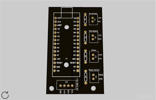
To easier the process, we create a printed circuit board to connect the Reed switch sensor and the three buttons. The PCB is presented below in Figure 2.
Figure 2 - Printed Circuit Board of the Project.
Looking at the PCB, it is possible to see the Arduino Nano. It is responsible to control all systems. In addition, we have 5 JST connectors.
The C1 until C4 connectors are used to connect the three buttons and the Reed Switch Sensor. Now, the C5 Connector is used to connect the LCD 16x2 I2C.
Therefore, through this system, you can install the project in your bicycle and obtain the traveled distance value.
For this, you can use the code presented below.
#include <EEPROM.h>
#include <LiquidCrystal.h>
/*
Pinos de conex?o dos bot?es e sensor reed switch
8 — Sensor Reed Switch
9 — Decremento
12 — Incremento
11 — Enter
*/
#define MEMORIA 120
#define PosRaio 125
#define ReedSwitch 8
#define BotaoEnterOk 11
#define BotaoIncremento 12
#define BotaoDecremento 9
const int rs = 2, en = 3, d4 = 4, d5 = 5, d6 = 6, d7 = 7;
LiquidCrystal lcd(rs, en, d4, d5, d6, d7);
bool sensor = 0, estado_anterior = 0, Incremento = 0, Decremento = 0;
bool IncrementoAnterior = 0, DecrementoAnterior = 0, BotaoEnter = 0, EstadoAnteriorIncremento = 0;
byte cont = 0;
unsigned long int VoltaCompleta = 0;
unsigned long int tempo_atual = 0, ultimo_tempo = 0;
float DistKm = 0;
unsigned int raio = 0;
float Distancia = 0;
void setup()
{
Serial.begin(9600);
pinMode(8, INPUT);
pinMode(9, INPUT);
pinMode(10, INPUT);
pinMode(12, INPUT);
lcd.begin(16,2);
//Regiao de codigo para configurar o raio da roda do veiculo
if(EEPROM.read(MEMORIA) != 73)
{
ConfiguraRaio();
EEPROM.write(MEMORIA, 73);
}
lcd.setCursor(3,0);
lcd.print(“Distancia”);
lcd.setCursor(6,1);
lcd.print(Distancia);
lcd.setCursor(14,1);
lcd.print(“km”);
raio = EEPROM.read(PosRaio);
}
void loop()
{
//Regiao de codigo para realizar a leitura dos botoes e sensor do dispositivo
sensor = digitalRead(ReedSwitch);
Decremento = digitalRead(BotaoDecremento);
Incremento = digitalRead(BotaoIncremento);
//Regiao de codigo para acumular a distancia percorrida
if(sensor == 0 && estado_anterior == 1)
{
VoltaCompleta++;
Distancia = (float)(2*3.14*raio*VoltaCompleta)/100000.0;
lcd.setCursor(0,1);
lcd.print(“ “);
lcd.setCursor(6,1);
lcd.print(Distancia);
lcd.setCursor(14,1);
lcd.print(“km”);
estado_anterior = 0;
}
if(sensor == 1 && estado_anterior == 0)
{
estado_anterior = 1;
}
//Regiao de Codigo para Configurar o Raio
if(Incremento == 1 && EstadoAnteriorIncremento == 0)
{
EstadoAnteriorIncremento = 1;
}
if(Incremento == 0 && EstadoAnteriorIncremento == 1)
{
EstadoAnteriorIncremento = 0;
lcd.clear();
ConfiguraRaio();
}
}
void ConfiguraRaio()
{
byte RaioRoda = 0;
//Imprimir mensagem para digitar o raio em cm
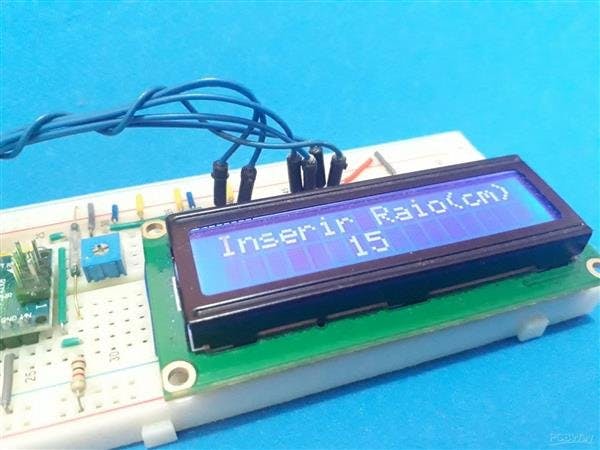
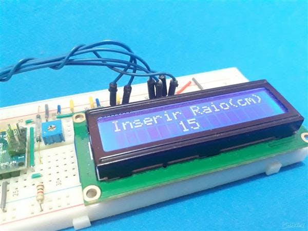
lcd.setCursor(0,0);
lcd.print(“Inserir Raio(cm)”);
do
{
lcd.setCursor(6,1);
Incremento = digitalRead(BotaoIncremento);
Decremento = digitalRead(BotaoDecremento);
BotaoEnter = digitalRead(BotaoEnterOk);
if(Incremento == 1 && IncrementoAnterior == 0)
{
RaioRoda = RaioRoda + 1;
IncrementoAnterior = 1;
}
if(Incremento == 0 && IncrementoAnterior == 1)
{
IncrementoAnterior = 0;
}
if(Decremento == 1 && DecrementoAnterior == 0)
{
RaioRoda = RaioRoda — 1;
DecrementoAnterior = 1;
}
if(Decremento == 0 && DecrementoAnterior == 1)
{
DecrementoAnterior = 0;
}
lcd.setCursor(6,1);
lcd.print(RaioRoda);
}while(BotaoEnter == 0);
lcd.clear();
EEPROM.write(PosRaio, RaioRoda);
return;
}
From this code it will possibly calculate your distance with your Arduino.
Conclusion
If you want your own PCB, you can get on through the PCBWay website. For this, you can access the website, create your account, and obtain your own PCBs.
The Silícios Lab also thanks UTSOURCE for the electronic components used to create this project.