Why this project :
I wanted to have an alarm for major storms that cause power outages lasting more than 2.5 hours. I'll only use it while I'm sleeping. But the delay before the alarm sounds can be easily modified in the Arduino Nano code.
How the Alarm Works
The alarm uses an Arduino Nano board that monitors the presence of power in the house by connecting it to a power supply plugged into a wall outlet. A USB backup power supply allows the alarm to sound an alert with a buzzer when the DC power from the power supply is no longer detected.
I had a 12 volt DC power supply on hand so this what I used. I used two resistors to reduce the voltage under 5 volts as the Nano cannot take more voltage.
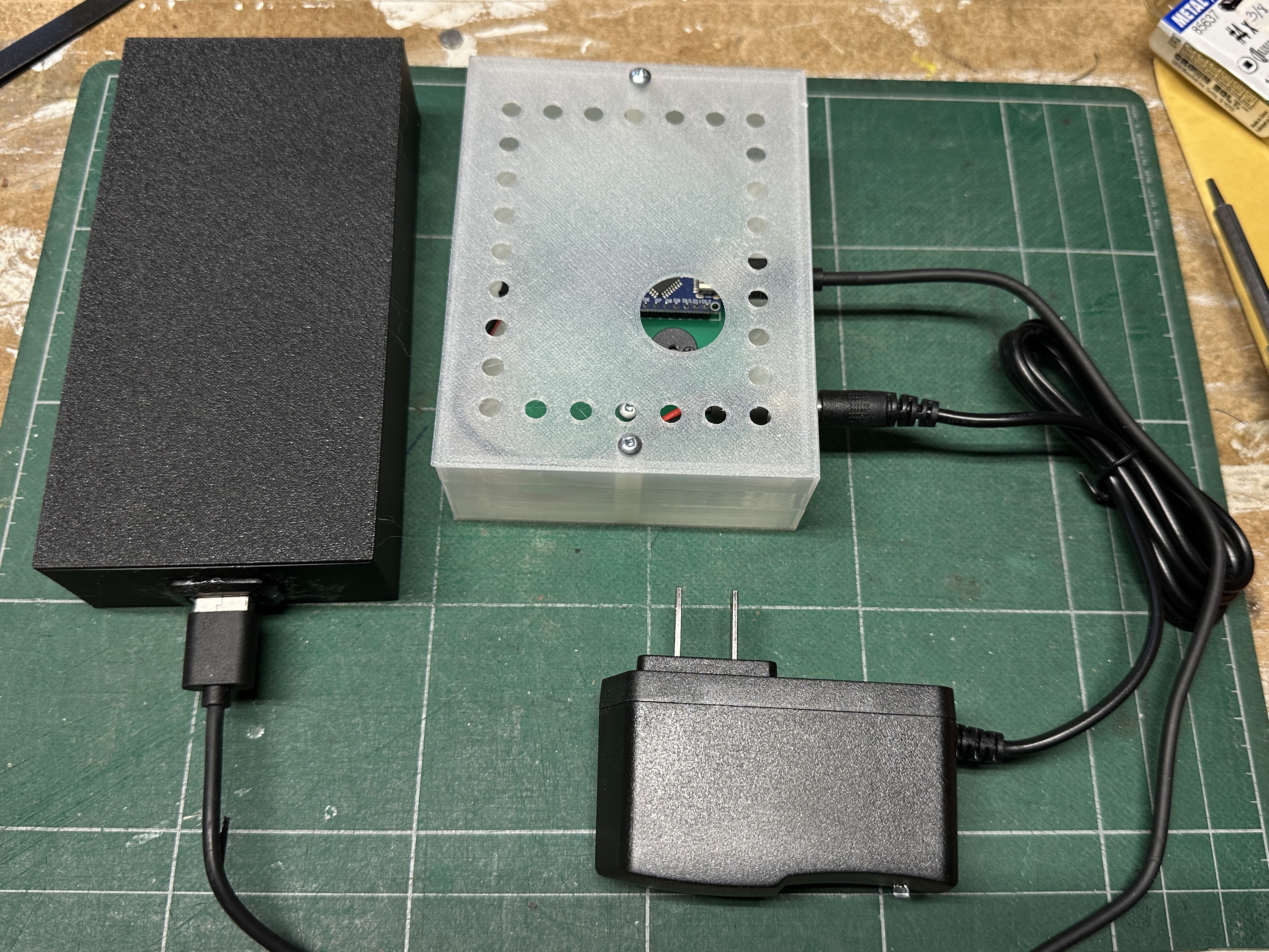
The alarm consists of two boxes that I designed and 3D printed. The first box contains the circuit board with an Arduino Nano. The USB backup power supply is in the second box and is connected to the Nano via its USB connector.
How to use it
First plug the power supply in the wall outlet. The green led on the PCB will light up. Plug in the alarm USB cable to the Power Bank. The status red led on the Nano will light up. When the circuit detects a power outage, it will sound an alarm for 30 seconds and the green led will flash alike. If there is a shorter power outage than the set value in the code, the alarm will reset on standby.
List of components
1 Arduino Nano V2
1 Led (I use Green)
1 active Buzzer 5v
3 Resistors : 220Ω , 10kΩ, 22kΩ
1 DC power supply to get 5 volt to the Nano by a wall outlet
1 DC-DC stepdown power module if the power supply is more than 5 volts DC.
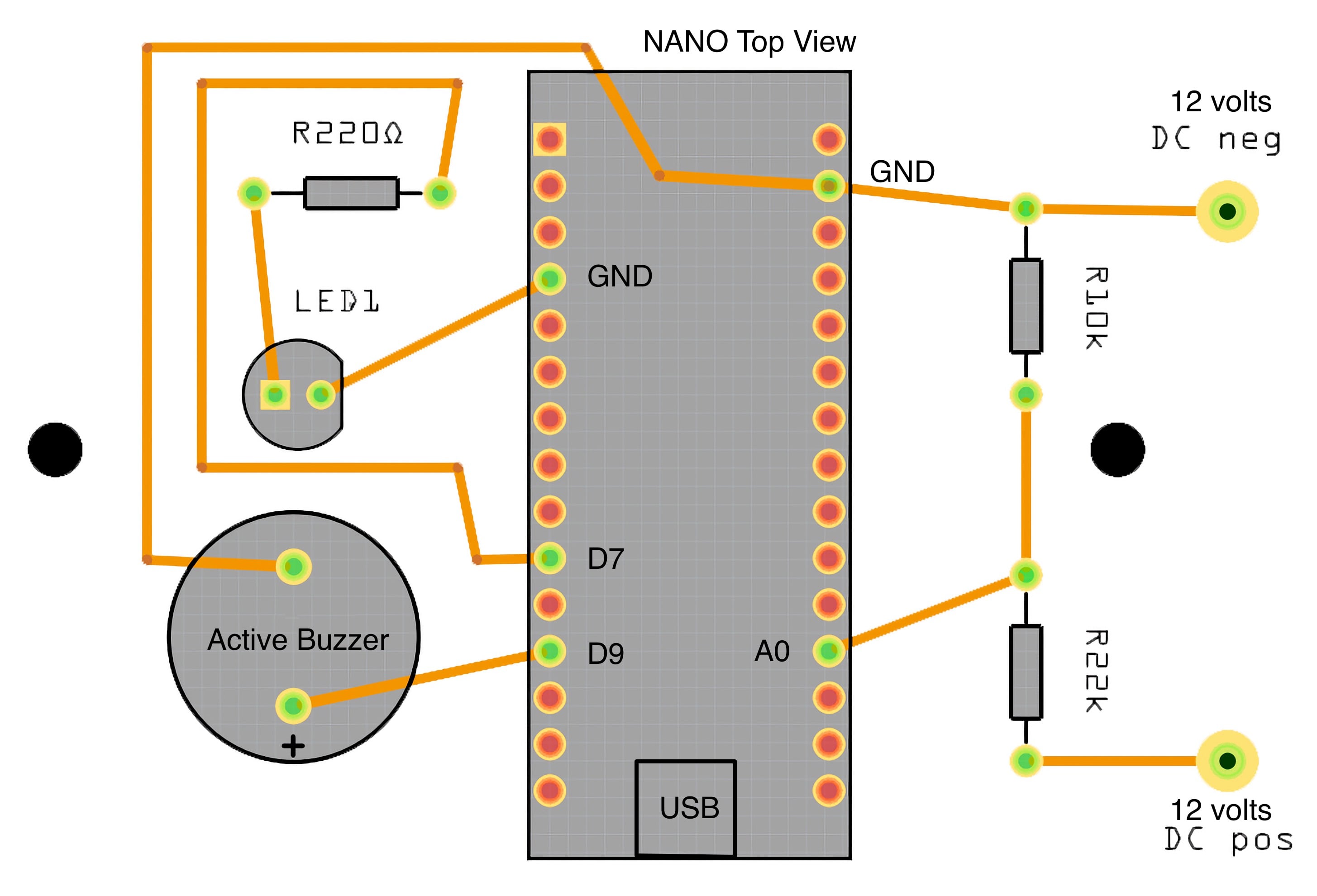
Here are the connections to the Nano
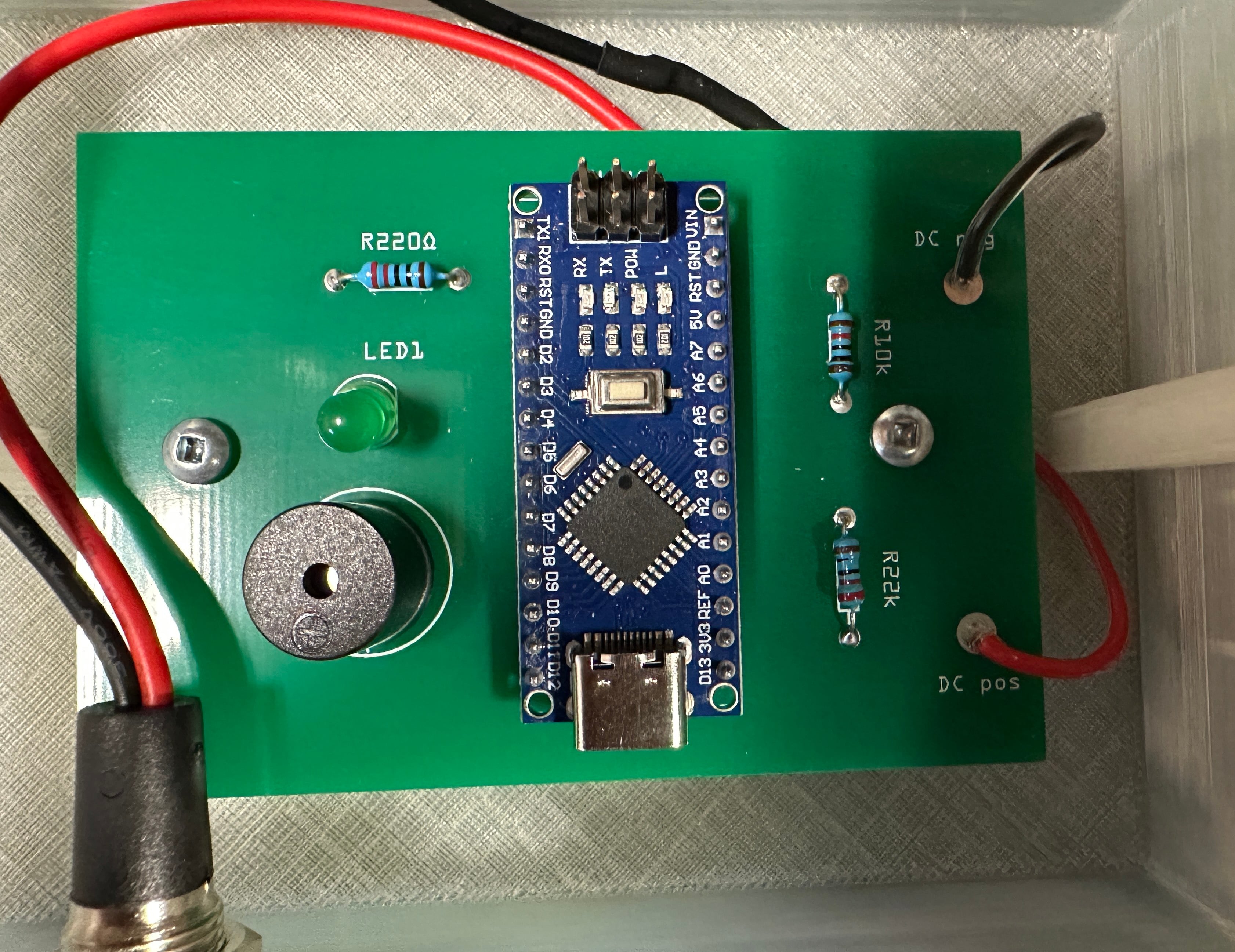
You can adjust the value of the resistors in the voltage divider to use a different voltage power supply. It is important that the voltage is not over 5 volt at pin A0. Here is a picture of the PCB with the solderded components.
The PCB with all the parts.
The code
I used Arduino IDE to load the code on the Nano. You can alter the value at line 46 (delay(10000);\) to change the delay before the alarm sounds. In the code the delay is set in thousands of seconds. It is set at 10 seconds witch gives a value of 10000. For a 10 minutes delay it would be 600000, and one hour 3600000.
// Define pins\
#define POWER_LED 7\
#define BUZZER 9\
#define POWER_SUPPLY A0\
\
// Set initial states\
int powerState = 0; // 0 for no power, 1 for power present\
int alarmState = 0; // 0 for no alarm, 1 for alarm active\
int ledState = 0; // 0 for LED off, 1 for LED on\
\
void setup() \{\
  // Set pin modes\
  pinMode(POWER_LED, OUTPUT);\
  pinMode(BUZZER, OUTPUT);\
  pinMode(POWER_SUPPLY, INPUT);\
  \
  // Turn off LED and buzzer\
  digitalWrite(POWER_LED, LOW);\
  digitalWrite(BUZZER, LOW);\
\}\
\
void loop() \{\
  // Check power supply voltage\
  int voltage = analogRead(POWER_SUPPLY);\
  \
  // If voltage is below 4V, set power state to 0\
  if (voltage < 800) \{\
    powerState = 0;\
  \}\
  // If voltage is above 4V, set power state to 1\
  else \{\
    powerState = 1;\
  \}\
  \
  // If power is present, turn on LED and turn off alarm\
  if (powerState == 1) \{\
    digitalWrite(POWER_LED, HIGH);\
    digitalWrite(BUZZER, LOW);\
    alarmState = 0;\
  \}\
  // If power is not present, turn off LED and check alarm state\
  else \{\
    digitalWrite(POWER_LED, LOW);\
    // If alarm is not active, start alarm after 10 seconds\
    if (alarmState == 0) \{\
      delay(10000);\
      alarmState = 1;\
    \}\
    // If alarm is active, alternate between buzzer on and off for 30 seconds\
    if (alarmState == 1) \{\
      for (int i = 0; i < 30; i++) \{\
        digitalWrite(BUZZER, HIGH);\
        delay(1000);\
        digitalWrite(BUZZER, LOW);\
        delay(1000);\
      \}\
      // Turn off alarm and reset LED state\
      alarmState = 0;\
      ledState = 0;\
    \}\
  \}\
  \
  // Flash LED during alarm\
  if (alarmState == 1) \{\
    // Alternate between LED on and off every second\
    if (ledState == 0) \{\
      digitalWrite(POWER_LED, HIGH);\
      ledState = 1;\
    \}\
    else \{\
      digitalWrite(POWER_LED, LOW);\
      ledState = 0;\
    \}\
  \}\
  \
  // Add a comment referencing source of code\
  // Code adapted from https://www.arduino.cc/en/Tutorial/Blink\
\}}
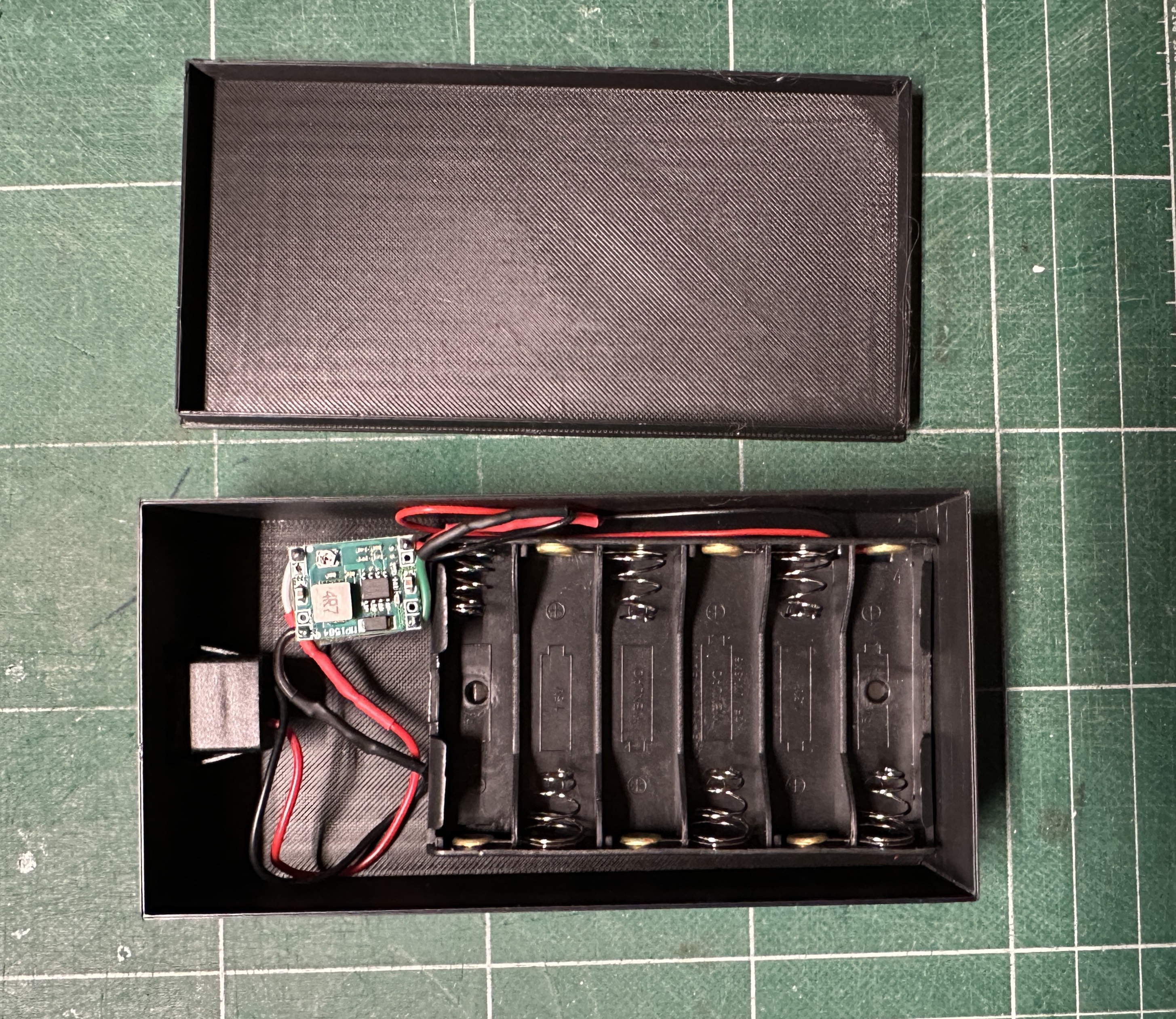
For the power bank I used a holder for 6 AA batteries with an adjustable Step Down Buke power module to give regulated 5 volt on the USB plug. But you can use a standard USB Power Bank, but make sure it wont go in sleep mode because this alarm circuit uses very litle current.
The DC-DC Step Down power module is conected between the USB female plug and the 6 AA battery holder.
Conclusion
This is my first attempt at electronics building and PCB design. I hope someone will find it useful, because I looked on many forums for an easy to build alarm and did not find a complete plan that suits my needs. I know there are cheaper chips that can be used for this project but Arduino is a great platform for beginners like me and you can get the Nano for 10$ online.