Using a free Raspberry Pi Pico emulator, learn Arduino style coding for Raspberry Pi Pico and membrane keypad.
Introduction to Raspberry Pi Pico simulator project
Raspberry Pi Pico is a tiny low cost MCU from Raspberry! It is tiny but very user friendly. It has following features
Below are the features of the RP2040 microcontroller:
- Dual ARM Cortex-M0+ @ 133MHz
- 264kB on-chip SRAM in six independent banks
- Support for up to 16MB of off-chip Flash memory via dedicated QSPI bus
- DMA controller
- Fully-connected AHB crossbar
- Interpolator and integer divider peripherals
- On-chip programmable LDO to generate core voltage
- 2 on-chip PLLs to generate USB and core clocks
- 30 GPIO pins, 4 of which can be used as analogue inputs
- Peripherals ◦ 2 UARTs ◦ 2 SPI controllers ◦ 2 I2C controllers ◦ 16 PWM channels ◦ USB 1.1 controller and PHY, with host and device support ◦ 8 PIO state machines
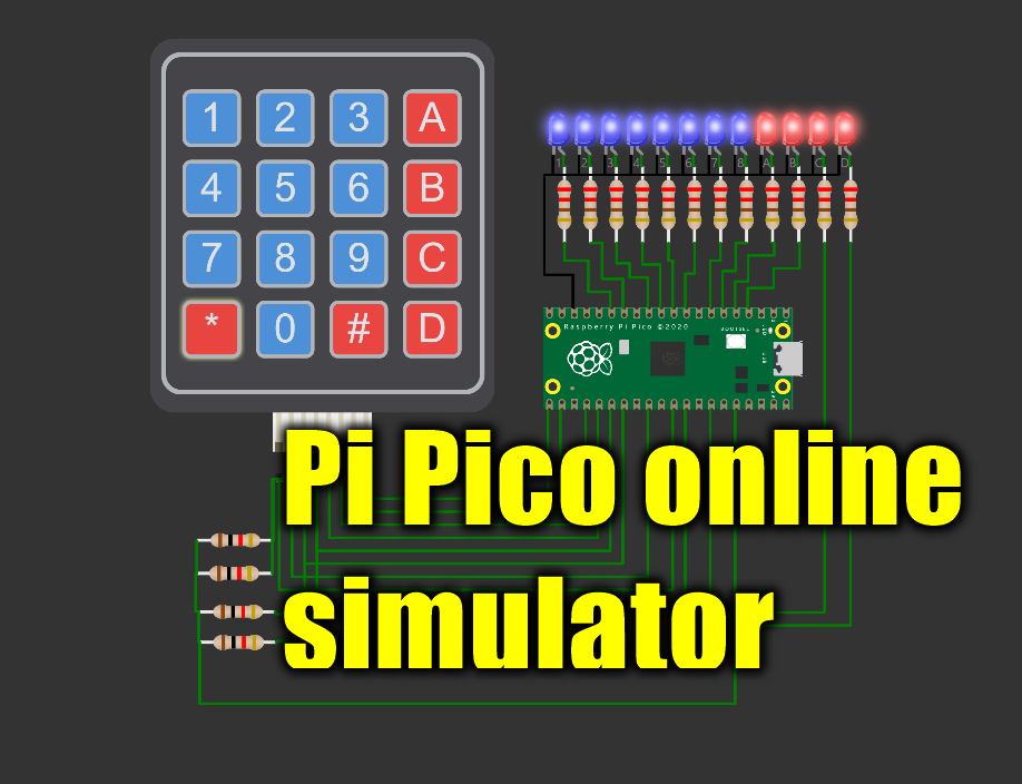
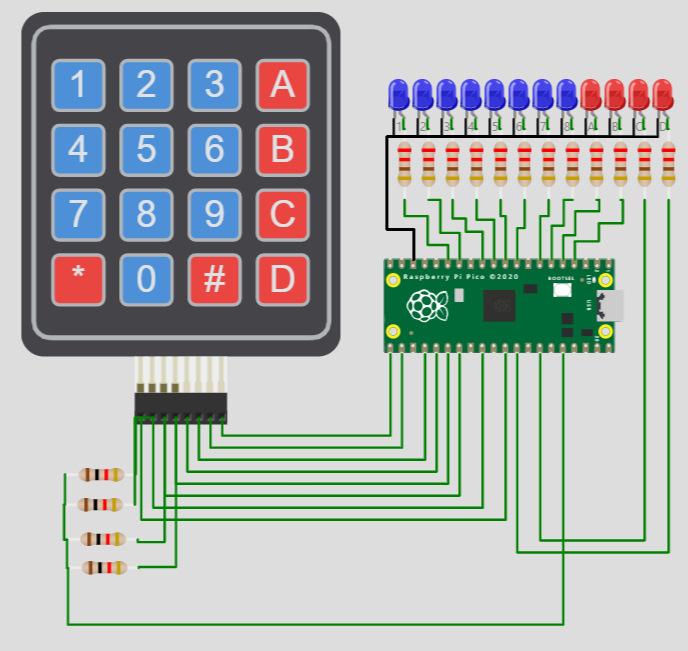
About the Pi Pico and Keypad interface project
The project is a simple application which interfaces a membrane keypad to the Pi Pico board. there are 8 blue LEDs mapped to numbers 1 to 8 on the keypad. The complete code is made available in the below section.
- When you press any digit on the keypad, the LED corresponding to the pressed digit will glow. To reset all the blue LEDs, press the 0 button.
- Press 1 to turn on LED1
- Press 2 to turn on LED2 and so on
- Pressing the * will turn on all the four RED LEDs
- Pressing # button will turn off all the red LEDs
- A,B,C and D are individually mapped to four RED LEDs in the same way
The connection diagram is given in the next section
Wokwi Raspberry Pi Pico simulator - Keypad membrane and LEDs interface on Pi Pico emulator
The code
#include <Keypad.h>

const uint8_t LEDS = 12;
const uint8_t ROWS = 4;
const uint8_t COLS = 4;

char keys[ROWS][COLS] = {
  { '1', '2', '3', 'A' },
  { '4', '5', '6', 'B' },
  { '7', '8', '9', 'C' },
  { '*', '0', '#', 'D' }
};

// Pins connected to LED1, LED2, LED3, ...LED12
uint8_t ledPins[LEDS] = { 11, 10, 9, 8, 7, 6, 5, 4, 3, 2, 28, 27 };
uint8_t rowPins[ROWS] = { 26, 22, 21, 20 }; // Pins connected to R1, R2, R3, R4
uint8_t colPins[COLS] = { 19, 18, 17, 16 }; // Pins connected to C1, C2, C3, C4

Keypad keypad = Keypad(makeKeymap(keys), rowPins, colPins, ROWS, COLS);

void setup() {
  for (uint8_t l = 0; l < LEDS; l++) {
    pinMode(ledPins[l], OUTPUT);
    digitalWrite(ledPins[l], LOW);
  }
}

void loop() {
  char key = keypad.getKey();

  if (key != NO_KEY) {
    switch (key) {
      case '1': digitalWrite(ledPins[0], HIGH);
        break;
      case '2': digitalWrite(ledPins[1], HIGH);
        break;
      case '3': digitalWrite(ledPins[2], HIGH);
        break;
      case '4': digitalWrite(ledPins[3], HIGH);
        break;
      case '5': digitalWrite(ledPins[4], HIGH);
        break;
      case '6': digitalWrite(ledPins[5], HIGH);
        break;
      case '7': digitalWrite(ledPins[6], HIGH);
        break;
      case '8': digitalWrite(ledPins[7], HIGH);
        break;
      case '9':
        for (uint8_t l = 0; l < 8; l++) {
          digitalWrite(ledPins[l], HIGH);
        }
        break;
      case '0':
        for (uint8_t l = 0; l < 8; l++) {
          digitalWrite(ledPins[l], LOW);
        }
        break;
      case 'A': digitalWrite(ledPins[8], HIGH);
        break;
      case 'B': digitalWrite(ledPins[9], HIGH);
        break;
      case 'C': digitalWrite(ledPins[10], HIGH);
        break;
      case 'D': digitalWrite(ledPins[11], HIGH);
        break;
      case '*':
        for (uint8_t l = 8; l < 12; l++) {
          digitalWrite(ledPins[l], HIGH);
        }
        break;
      case '#':
        for (uint8_t l = 8; l < 12; l++) {
          digitalWrite(ledPins[l], LOW);
        }
        break;
    }
  }
}
Here is the Pi Pico simulation output
membrane keypad interface and Pi Pico interface - simulation output
Feedback and comments on the Pi Pico emulator
Please share your feedback on the project and the Raspberry Pi Pico emulator from the Wokwi website. You can have more information on the Raspberry Pi Pico simulator here.
If you have any questions, please hop on to the Wokwi Discord server. Please visit Electrotantra YouTube channel for more videos on the Arduino and Raspberry Pi Pico simulators.
Thank you ?