Learn how to implement a feature to monitor the real-time clock battery and prevent problems.
On several systems that use time and date to perform certain tasks, it is critical to use real-time clock chips.
But one of the big problems is that it needs a battery to, keep the time and date count when the system is off.
On the computer, for example, we have a Real-Time Clock and when the battery is low voltage, the time and date are displayed with wrong values.
So, to solve this problem in projects, we can monitor the battery voltage.
Thus, when the battery is below a limit value, the system will generate an alarm in order to perform the exchange.
In this article, we will create a system to monitor the battery and generate an alarm for the user to change the battery.
To construct this project you'll need the following electronic components.
Supplies:
Project Development
In this project, we will create a complete system of configuration and presentation of the date and time. Our goal is to present only the date and hour and, mainly, to focus on monitoring the battery of the real-time clock.
With this monitoring, we will display its voltage value while the date and time are displayed on the LCD.
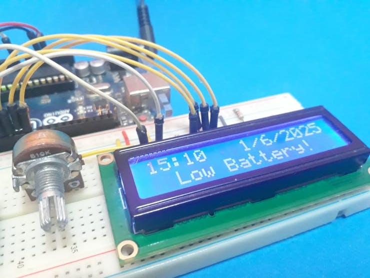
Case the voltage value is less than 1.5V, the system will alert the user, to inform a voltage low level of the battery.
Hereafter, we present the screen with an alert message of a low level of voltage in Figure 1.
Figure 1 - Screen with a message of the low level of voltage.
Now, we will present the step by step process to construct a simple project using Arduino UNO.
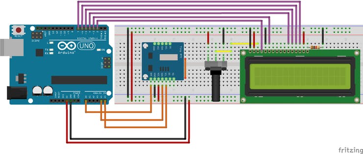
To construct this project, you need to use this circuit presented in Figure 2.
Figure 2 - Circuit Electronic Schematic to monitor the Battery Voltage.
Through this circuit, see that in the Real-Time Clock module have a pin named of VBat. With this pin, we connect in the analog pin AN0 to verify the battery voltage and to inform in LCD 16 x 2.
Now, see the project and we will learn how the code works. The code is presented below.
#include <LiquidCrystal.h>
#include <Wire.h>
#include "RTClib.h"

RTC_DS1307 rtc;

const int rs = 2, en = 3, d4 = 4, d5 = 5, d6 = 6, d7 = 7;
LiquidCrystal lcd(rs, en, d4, d5, d6, d7);

#define tensao A0

bool ControlVbat1 = 0, ControlVbat2 = 0;

void setup ()
{
 lcd.begin(16,2);
 Serial.begin(9600);
 if (! rtc.begin())
 {
   Serial.println("DS1307 não encontrado");
   while(1);
 }
 if (! rtc.isrunning())
 {
   Serial.println("DS1307 rodando!");
   rtc.adjust(DateTime(2025, 6, 1, 15, 00, 00)); //Year, Month, Day, Minutes and Seconds
 }
 pinMode(tensao, INPUT);
}

void loop ()
{
   float Vbat = (5*(analogRead(tensao)))/1023;

   DateTime now = rtc.now();
   lcd.setCursor(0,0);

   if(now.hour() < 10)
   {
    lcd.setCursor(0,0);
    lcd.print("0");
   }

   lcd.print(now.hour(), DEC );
   lcd.print(":");

   if(now.minute() < 10)
   {
    lcd.setCursor(3,0);
    lcd.print("0");
   }

   lcd.print(now.minute(), DEC);
   lcd.setCursor(8,0);
   lcd.print(now.day(), DEC );
   lcd.print("/");
   lcd.print(now.month(), DEC);
   lcd.print("/");
   lcd.print(now.year(), DEC);
   if(Vbat < 1.5 && ControlVbat1 == 0)
   {
     lcd.setCursor(0,1);
     lcd.print("                ");
     lcd.setCursor(2,1);
     lcd.print("Low Battery!");
     ControlVbat1 = 1;
     ControlVbat2 = 0;
   }
   if(Vbat >= 1.5 && ControlVbat2 == 0)
   {
     lcd.setCursor(0,1);
     lcd.print("                ");
     lcd.setCursor(1,1);
     lcd.print("Voltage: ");
     lcd.print(Vbat);
     lcd.print("V");
     ControlVbat1 = 0;
     ControlVbat2 = 1;
   }
}
In this code, we made the configs of LCD, Real Time Clock, its hour initializations and variable declaration.
float Vbat = (5*(analogRead(tensao)))/1023;
After this, the data and hours are collected from the real-time clock module. And so, its values are presented in the LCD 16x2.
DateTime now = rtc.now();
   lcd.setCursor(0,0);

   if(now.hour() < 10)
   {
    lcd.setCursor(0,0);
    lcd.print("0");
   }

   lcd.print(now.hour(), DEC );
   lcd.print(":");

   if(now.minute() < 10)
   {
    lcd.setCursor(3,0);
    lcd.print("0");
   }

   lcd.print(now.minute(), DEC);
   lcd.setCursor(8,0);
   lcd.print(now.day(), DEC );
   lcd.print("/");
   lcd.print(now.month(), DEC);
   lcd.print("/");
   lcd.print(now.year(), DEC);
After present the value of date and hour, the system will verify if the battery voltage is less or more than 1.5V.
if(Vbat < 1.5 && ControlVbat1 == 0)
   {
     lcd.setCursor(0,1);
     lcd.print("                ");
     lcd.setCursor(2,1);
     lcd.print("Low Battery!");
     ControlVbat1 = 1;
     ControlVbat2 = 0;
   }
   if(Vbat >= 1.5 && ControlVbat2 == 0)
   {
     lcd.setCursor(0,1);
     lcd.print("                ");
     lcd.setCursor(1,1);
     lcd.print("Voltage: ");
     lcd.print(Vbat);
     lcd.print("V");
     ControlVbat1 = 0;
     ControlVbat2 = 1;
   }
If the voltage value was less than 1.5V, the LCD will present a message of Low Battery, as is presented in Figure 3.
In this way, the user will be alerted by the system.
Figure 3 - LCD presenting a message of Low Battery.
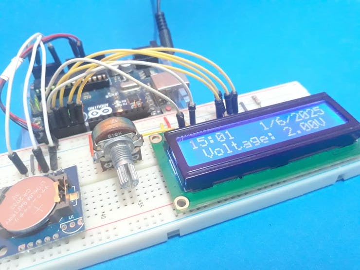
Now, case the battery is with voltage more than 1.5V, the LCD will present the date, time, and voltage of the battery.
This is presented in Figure 4.
Figure 4 - Screen presenting the hours and battery voltage.
The variables ControlVbat1 and ControlVbat2 are used to present the message only one time in the LCD.
In this way, these variables prevent the message be presented several times and occur in-desiring effects in the LCD.
Therefore, we can use this design to monitor battery operation and avoid time failures in applications that require the correct date and time operation.
In this way, when alerting the user, it may change the battery and maintain the proper operation of the equipment.
Acknowledgment
Thanks to the PCBWay for supporting our YouTube channel.
The Silícios Lab thanks UTSOURCE for providing the electronic components.