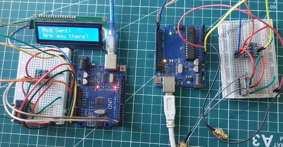
In this project, you’ll learn how to interface the Reyax RYLR999 LoRa module with an Arduino UNO.
Why Choose LoRa for Your Projects?
LoRa is a wireless modulation technique designed to maximize range and battery life rather than high data throughput. It uses Chirp Spread Spectrum (CSS) modulation to make signals robust against noise and interference. LoRa typically operates in license-free ISM bands such as 433 MHz, 868 MHz, and 915 MHz, allowing devices to communicate over 10+ km in open environments with minimal power draw.
Because LoRa handles only the physical layer, higher-level features such as device addressing and network management must be implemented in software—often using simple AT-style commands.
Reyax RYLR999 Module
The RYLR999 Lite combines:
- A 915/868 MHz LoRa transceiver
- A 2.4 GHz BLE interface
- Each interface has its own UART channel, allowing independent LoRa and BLE communication.
You can configure the module via AT commands: set frequency, network ID, addresses, and modulation settings. Because it supports BLE-to-LoRa bridging, you can even send data from a smartphone app over LoRa by routing BLE traffic into the LoRa UART.
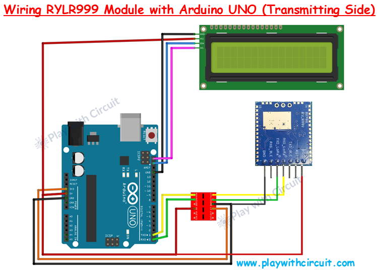
Wiring the Initiator (Transmitter)
Power
- Arduino 5V → RYLR999 VDD
- Arduino GND → RYLR999 GND
UART (via Bi-Directional Voltage Shifter)
Because the Arduino operates at 5V logic and the RYLR999 at 3.3V, you must insert a voltage shifter between them:
- RYLR999 TXD_LoRa → Arduino RX (via voltage shifter)
- Arduino TX → RYLR999 RXD_LoRa (via voltage shifter)
- Arduino 5V → HV, Arduino 3.3V → LV on the shifter
16×2 I2C LCD
- VCC → 5V
- GND → GND
- SDA → A4
- SCL → A5
- Make sure the I2C address jumpers A0/A1/A2 are not shorted for address 0x27 (used in code).
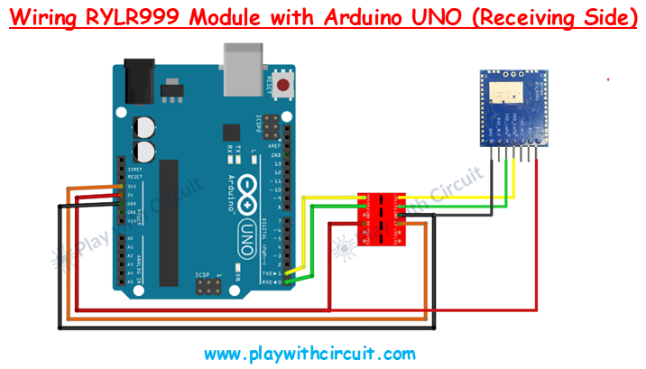
Wiring the Responder (Receiver)
The responder’s wiring is identical to the initiator’s except it does not require an LCD:
- Same UART wiring with voltage shifter
- Same power connections
- No I2C LCD connections
This Arduino simply listens for “Are you there?”, then sends back “Yes”.
Arduino Code for Initiator Setup
/*
Code to send “Are you there?” from one Arduino to another Arduino using RLYR999 Module
and receive reply and display complete communication on I2C LCD by platwithcircuit.com
*/
#include <LiquidCrystal_I2C.h>
#define REPLY_TIMEOUT_IN_MS 300
#define REPLY_END_CHAR '\n'
#define MODULE_ADDRESS 0
#define RECEIVERS_ADDRESS 1
#define MIN_CHAR_TO_RCV 1
#define WAIT_FOR_RECIVERS_REPLY 3000
#define DELAY_BW_REPS 1000
// Init LCD at 0x27, 16x2
LiquidCrystal_I2C lcd(0x27, 16, 2);
void setup() {
  boolean boRetVal = false;
  // begin serial communication at baud 115200,n,8,1
  // to communicate with the RF module
  Serial.begin(115200);
  // initialize the LCD
  lcd.init();
  // Turn ON the Backlight
  lcd.backlight();
  // Clear the display buffer
  lcd.clear();
  flushBuffer();  // clear rx data
  // Reset settings to factory defaults
  boRetVal = boRestoreFactoryDefaults();
  // setting the address if reset successfully
  if (boRetVal == true) {
    flushBuffer();  // clear rx data
    boRetVal = boSetAddress();
  }
  if (boRetVal == true) {
    lcd.clear();
    lcd.setCursor(0, 0);
    lcd.print("Module Init");
    lcd.setCursor(0, 1);
    lcd.print("Successful");
    delay(1000);
  } else {
    lcd.clear();
    lcd.setCursor(0, 0);
    lcd.print("Module Init");
    lcd.setCursor(0, 1);
    lcd.print("Failed");
    while (1)
      ;
  }
}
void loop() {
  String request = "Are you there?";
  String expected_reply = "Yes";
  bool boRetVal = false;
  flushBuffer();  // clear rx data
  // transmits String named request
  boRetVal = boSendData(request);
  if (boRetVal == true) {
    // Displaying Sent Msg
    lcd.clear();
    lcd.setCursor(0, 0);
    lcd.print("Msg Sent:");
    lcd.setCursor(0, 1);
    lcd.print(request);
    delay(1000);
    boRetVal = chkReply(expected_reply, REPLY_END_CHAR, WAIT_FOR_RECIVERS_REPLY);
    if (boRetVal == true) {
      // Displaying received Msg
      lcd.clear();
      lcd.setCursor(0, 0);
      lcd.print("Msg Received:");
      lcd.setCursor(0, 1);
      lcd.print(expected_reply);
    } else {
      lcd.clear();
      lcd.setCursor(0, 0);
      lcd.print("No reply received.");
    }
  } else {
    // Displaying Failed Msg
    lcd.clear();
    lcd.setCursor(0, 0);
    lcd.print("Msg Sending");
    lcd.setCursor(0, 1);
    lcd.print("Failed");
  }
  delay(DELAY_BW_REPS);  // wait before sending again
}
void sendCrLf(void) {
  Serial.write(0x0D);  // Carriage Return
  Serial.write(0x0A);  // Line Feed
}
void flushBuffer(void) {
  while (Serial.available() > 0) {
    Serial.read();
  }
}
bool chkReply(String chkString, char receiveUntil, unsigned int timeout) {
  String receivedString;       // save received data in this string object
  bool boReturnValue = false;  // function's return value
  // wait for reply
  do {
    timeout--;
    delay(1);  // delay of 1 ms
  } while ((Serial.available() < MIN_CHAR_TO_RCV) && (timeout > 0));
  if (timeout) {
    // if timeout is left then a reply is received check for the string in the reply
    receivedString = Serial.readStringUntil(receiveUntil);
    if (receivedString.indexOf(chkString) != -1) {
      boReturnValue = true;
    } else {
      boReturnValue = false;
    }
  } else {
    boReturnValue = false;
  }
  // return result
  return boReturnValue;
}
bool boRestoreFactoryDefaults(void) {
  const char factoryDefaultCmd[] = "AT+FACTORY";  // command to be sent
  bool boReturnValue = false;                     // function's return value
  char downCounter = 100;                         // Down counter to wait for reply
  String receivedString;                          // save received data in this string object
  String chkRcvString1 = "+FACTORY";
  String chkRcvString2 = "+READY";
  // send command
  Serial.print(factoryDefaultCmd);
  sendCrLf();
  // check first string in reply
  boReturnValue = chkReply(chkRcvString1, REPLY_END_CHAR, REPLY_TIMEOUT_IN_MS);
  if (boReturnValue == true) {
    // check second string in reply
    boReturnValue = chkReply(chkRcvString2, REPLY_END_CHAR, REPLY_TIMEOUT_IN_MS);
  }
  // return result
  return boReturnValue;
}
bool boSetAddress(void) {
  const char setAddressCmd[] = "AT+ADDRESS=";  // command to be sent
  bool boReturnValue = false;                  // function's return value
  String chkRcvString = "+OK";
  // send command
  Serial.print(setAddressCmd);
  Serial.print(MODULE_ADDRESS);
  sendCrLf();
  // check reply
  boReturnValue = chkReply(chkRcvString, REPLY_END_CHAR, REPLY_TIMEOUT_IN_MS);
  // return result
  return boReturnValue;
}
bool boSendData(String data) {
  const char sendDataCmd[] = "AT+SEND=";  // command to be sent
  bool boReturnValue = false;             // function's return value
  String chkRcvString = "+OK";
  // send command
  Serial.print(sendDataCmd);
  Serial.print(RECEIVERS_ADDRESS);
  Serial.print(',');
  Serial.print(data.length());
  Serial.print(',');
  Serial.print(data);
  sendCrLf();
  // check reply
  boReturnValue = chkReply(chkRcvString, REPLY_END_CHAR, REPLY_TIMEOUT_IN_MS);
  // return result
  return boReturnValue;
}
Want the Full Project?
You’ll find complete Arduino code, detailed code explanations in the full tutorial on Play with Circuit.
Read the full guide here: https://playwithcircuit.com/how-to-interface-reyax-rylr999-lora-module-with-arduino/