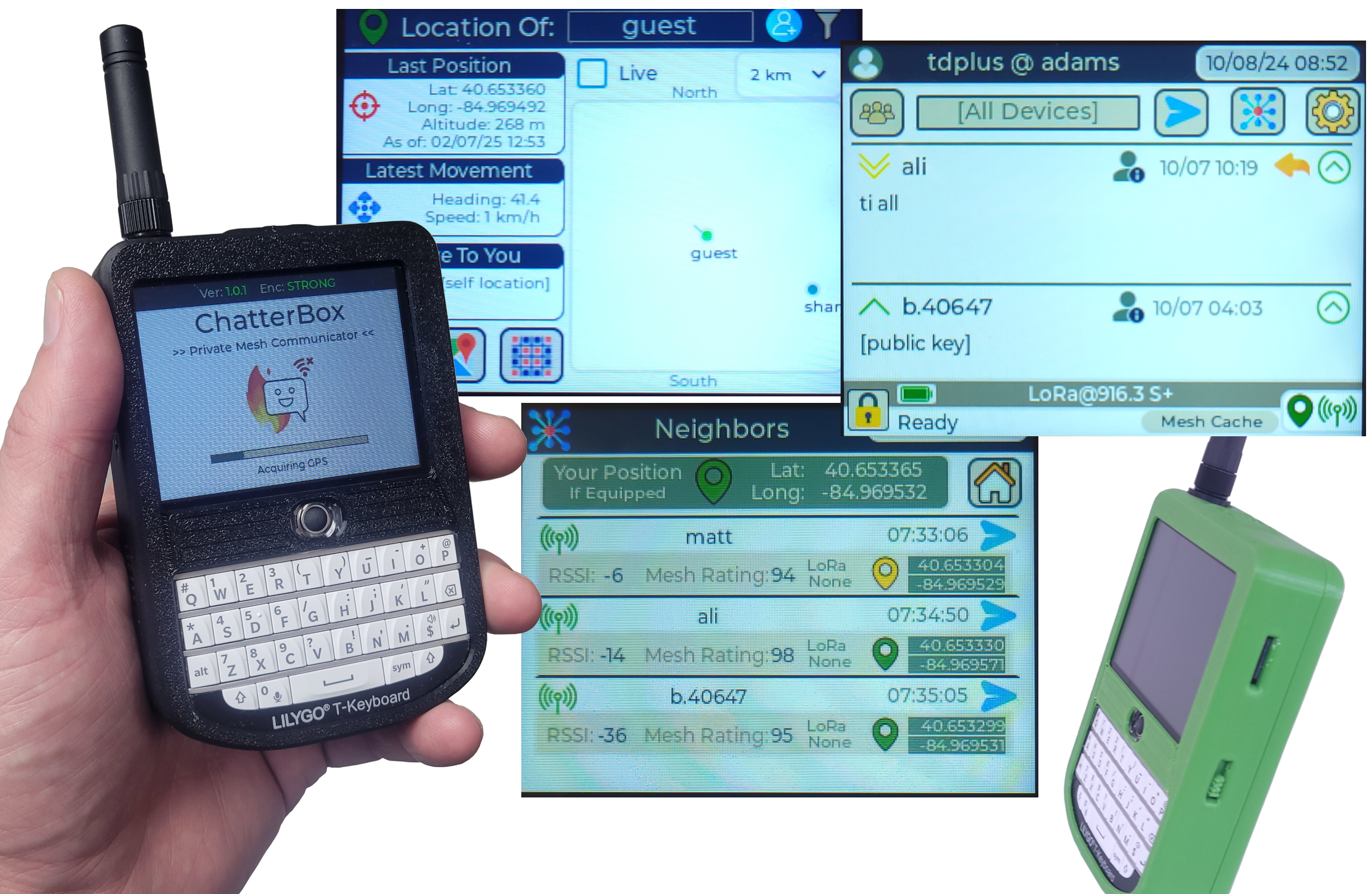
ChatterBox is an off-grid communication and location sharing system that allows you to stay in contact with other trusted people and nodes nearby, using LoRa frequencies, meshing, encryption, and digital signatures.
This project shows you how to build a ChatterBox communicator using Lilygo T-Deck, along with some other components.
You will want more than one communicator, so maybe grab a buddy to assemble more than one. These devices will be compatible with any other ChatterBox devices, including nodes (there are instructions for a good E-Paper node on this site), as well as already-assembled T-Deck+. The advantages of this over the T-Deck+ are that you'll have a nice realtime clock for added security and good functionality even if you can't acquire GPS, better battery, and obviously the external antenna for better range.
If you are comfortable with 3D printing, soldering, and electricity, this is a fairly simple project.
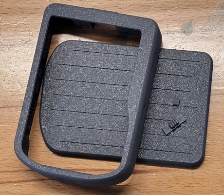
Step 1 - 3D Print or Acquire a Case
The case shown here is designed by AlleyCat. The 3D files attached to this project are slightly modified versions of that case, with the SD card slot moved a little and extra space for the plug on the side of the T-Deck.
If you don't have access to a 3D printer, you can purchase already-printed T-Deck cases on Etsy and elsewhere. However, many of them don't leave the SD card slot exposed or don't leave space for using the plug on the side (or have it open). Those may be issues you have to solve if you use a different case.
Note: The reset button may be more trouble than it's worth. You don't actually need access to the reset button, so if it's covered, that should be fine.
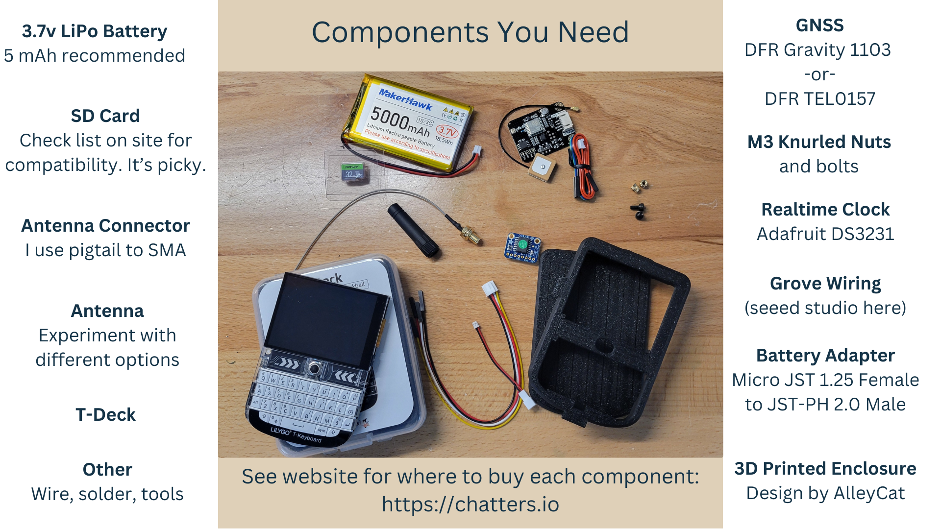
Step 2 - Gather (or acquire) all your Components
The list of components and links to sources is also available in the attached PDF. Most (sometimes all) components are available at Amazon.
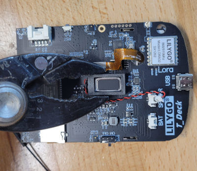
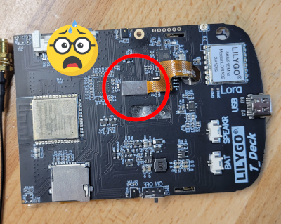
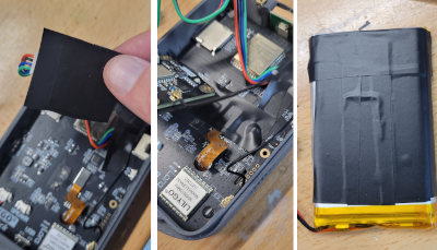
Step 3 - Move the Speaker
There is just a bit of tacky glue holding the speaker in place. It should come off without much trouble. You should probably use a small screwdriver to pry it off, rather than pliers (even though that's what the image shows).
We still want to keep the speaker, it's just kind of in the way being in the center like this.
Careful Not To Dislodge this Connector!
If you do dislodge it, just carefully press it back into place. It's so small, it can be tricky.
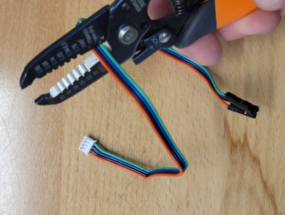
Step 4 - Cut the DFR cable
From the DFR cable, we are only going to use the end with the white plug, which connects directly to the DFR module. Cut the cable so you are left with about 3.5 to 4 inches.
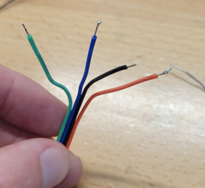
Step 5 - Separate, Strip, and Tin the wires
Separate the wire ends so each wire is free for around 1.5 inches. Twist and tin the end of each wire with a little solder.
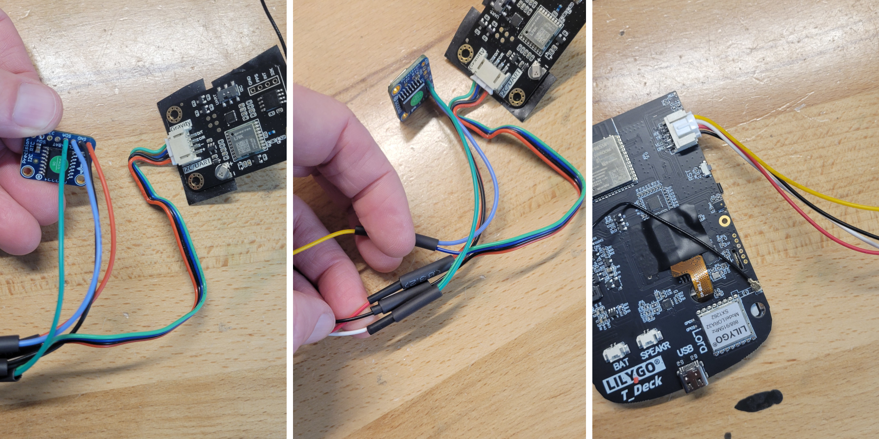
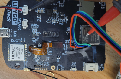
Step 6 - Connect Wires as Shown
I cover each soldered joint with heat shrink tubing. The above connections are:
- DFR + (red) : RTC VIN (red) : T-Deck VCC (red)
- DFR – (black) : RTC GND (black) : T-Deck GND (black)
- DFR C/R (blue) : RTC SCL (blue) : T-Deck RX (yellow)
- DFR D/D (green) : RTC SDA (green) : T-Deck TX (white)
Do not rely on wire colors, as adapters could have different colors in different orders. Use your own skill and the mappings mentioned above to determine the connections with your supplies.
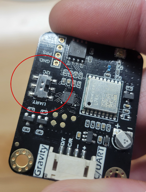
Step 7 - Switch DFR to I2C
Also, trim the switch, as it's pretty long and will poke into the battery.
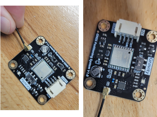
Step 8 - Connect the GPS Antenna
Step 9 - Trim the T-Deck Reset Button
This is important!
If you do not trim the reset button to be flush with the side of the T-Deck, the case will constantly be pressing the reset button.
The device will appear to be dead/bricked, only because the reset button is being held.
We do not need the reset button! Trim that thing down.
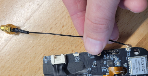
Step 10 - Attach the LoRa Pigtail Connector
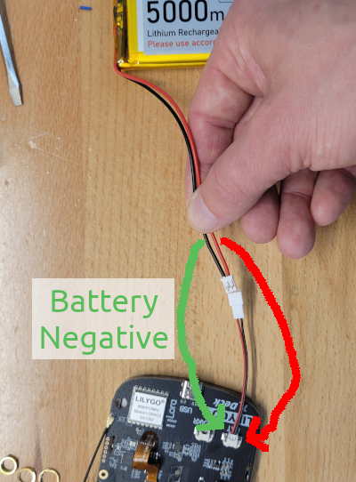
Step 11 - Double-Check the T-Deck Polarity
Step 12 - Connect the Battery
The T-Deck's battery connector polarity is not marked (at least not on any I've seen). So you'll need to check that somehow. I use continuity between the plug pin and the ESP32 cover, which is grounded.
In this image, I'm using a hack of an adapter to swap polarity to match the battery here. You may want to do something different.
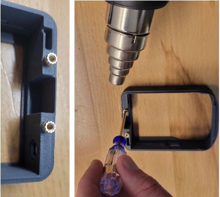
Step 13 - Press the Nuts Into Place
I don't use a heat gun for this anymore, although that does work. Instead, I use a soldering tip that has an m3-sized tip (found cheaply on Amazon) that fits nicely so nothing else gets hot besides the knurled nut.
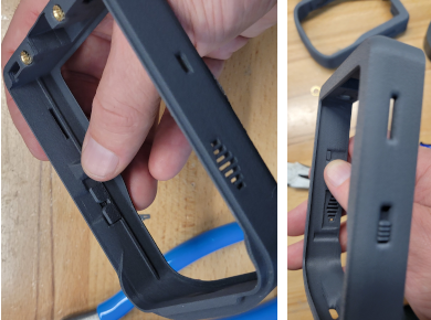
Step 14 - Press the Printed Buttons Into Place
These need to be able to move freely or you'll have trouble turning the thing off and on. So trim as necessary to get them moving.
As mentioned before, if the reset button is continually pressing/stuck, the device will not power on and will appear to be dead. So the reset button needs to move freely as well (or you can just leave it off if you prefer).
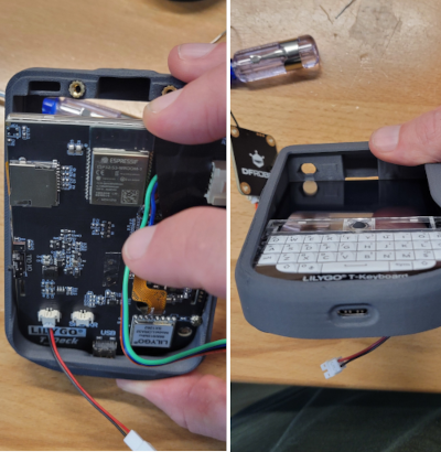
Step 15 - Insert the T-Deck
Don't forget to remove the protective screen cover!
As you might imagine, this is a tight fit and requires some finesse. To get it in, first align the USB micro port as shown in the image. Once you've got that aligned, you should be able to carefully work the T-Deck into place. You will probably need to apply outward pressure on various points of the enclosure as you do this.
Step 16 - Use Electrical Tape to Insulate Surfaces
Since we are leaving components "loose" inside this enclosure, anything that might cause a short because of how a component is situated needs to be insulated with something (i use electrical tape).
Just don't cover anything that's supposed to dissipate heat (the ESP32 cover, for instance).
After seeing a LiPo battery wrapper cause a short one time, I now cover the backside of the LiPo battery with electrical tape.
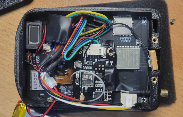
Step 17 - Insert All Components Except the Battery
You may want to use some adhesive to hold the GPS antenna in place. You can see I've also wrapped the RTC in electrical tape.
As you are pushing the LoRa SMA connector through its hole, notice the SMA connector will have a flattened side, which lines up with a flattened side of the enclosure's hole.
You will want to arrange the components so they will not be in the way of the battery. It may take a few tries to have things arranged well enough for the case to close easily.
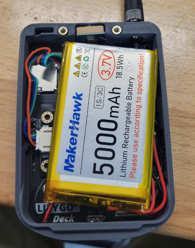
Step 18 - Connect the Battery
Add the battery, being careful not to put too much pressure on the battery, the internal components, or anything else. It's much easier to rearrange things now than it is once you've got it all together and working.
Batteries obviously come in different shapes and sizes. There are 3.7 LiPo 5000 mAh batters that are flatter and wider than what is shown here that also work fine. 5000 mAh is a little bit of overkill if you don't anticipate going for days without a charge, so you could get by with a smaller battery. If you decide to use a larger battery, check out Alley Cat's alternative covers that allow more space for larger capacity batteries.
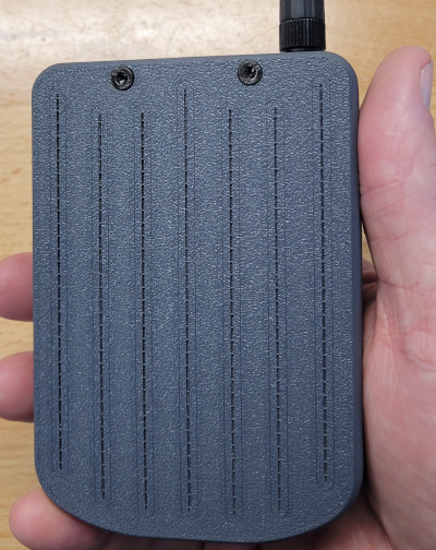
Step 19 - Install Back Cover
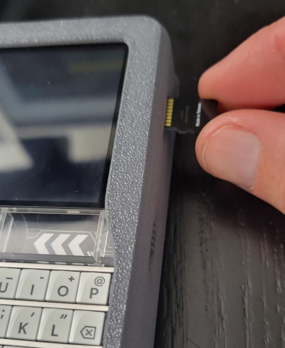
Step 20 - Install an SD Card
As of firmware version 1.6.8, this step is option, but still highly recommended for numerous reasons. If you don't use an SD card, the device's flash will be used for storing packets and other data that changes frequently. It does work, but larger capacity SD cards are better.
SD cards also allow you to backup your device settings so they can be recovered (to the same device).
If you use an SD card, know that T-Deck is very picky, and you should choose an SD card from the known compatible list.
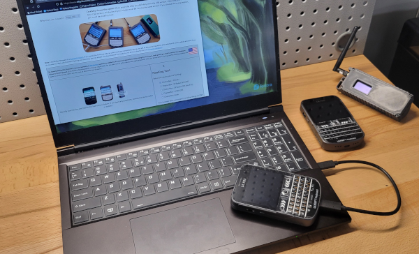
Step 21 - Install the ChatterBox Firmware
The firmware can be installed from any of these sites:
Last Step - Disconnect and Restart your New Communicator
You should be up and running, ready to create your new cluster or onboard your new device to an existing one.
For help setting up your device or cluster, check the ChatterBox support site.