In this project, you’ll learn how to interface a soil moisture sensor with an Arduino to measure the moisture level in the soil and display the readings.
How Does a Soil Moisture Sensor Work?
A soil moisture sensor works by measuring the moisture content in the soil using its two exposed conductive probes. These probes are inserted directly into the soil and act as a variable resistor. The resistance between the probes changes based on the soil's moisture level.
- Higher Moisture: When the soil has more water, it conducts electricity better, resulting in lower resistance. This indicates a higher moisture level.
- Lower Moisture: When the soil has less water, it conducts electricity poorly, leading to higher resistance. This corresponds to a lower moisture level.
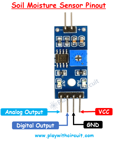
Soil Moisture Sensor Pinout
The soil moisture sensor module typically comes with four pins, each serving a specific purpose:
- VCC (Power Supply Pin): This pin is used to connect the sensor to a power source, typically 3.3V or 5V.
- GND (Ground Pin): This pin should be connected to the ground (GND) of the Arduino.
- DO (Digital Output Pin): This pin provides a digital signal (HIGH or LOW) based on the soil moisture level.
- AO (Analog Output Pin): This pin generates an analog voltage that varies proportionally with the soil moisture level, allowing precise measurements.
Wiring Soil Moisture Sensor in Analog Mode
Hardware Requirement
- Arduino UNO R3
- Soil Moisture sensor
- LCD 16x2
- Jumper Wires
- Breadboard
Circuit Diagram
In the wiring diagram, the Arduino UNO is connected with a soil moisture sensor and a 16×2 I2C LCD display:
Soil Moisture Sensor:
- The VCC pin of the sensor is connected to the 5V pin of the Arduino.
- The GND pin of the sensor is connected to the GND pin of the Arduino.
- The Analog Output (AO) pin of the sensor is connected to the analog input pin A0 of the Arduino.
16×2 I2C LCD Display:
- The SCL (Serial Clock Line) of the LCD is connected to the SCL pin of the Arduino.
- The SDA (Serial Data Line) of the LCD is connected to the SDA pin of the Arduino.
This setup allows the Arduino to read the soil moisture level and display the data on the LCD screen using the I2C communication protocol.
/*
Interfacing FC-28 Soil Moisture Sensor with Arduino UNO using is Analog Output pin of Module
by www.playwithcircuit.com
*/
// Library to Run I2C LCD
#include <LiquidCrystal_I2C.h>
// Set the LCD address to 0x27 for a 16 chars and 2 line display
LiquidCrystal_I2C lcd(0x27, 16, 2);
// Define the analog pin for the soil moisture sensor
const int soilMoisturePin = A0;
// Variables to store sensor values
int sensorValue = 0;
int moisturePercent = 0;
void setup()
  {
  // initialize the lcd
  lcd.init();
  // Turn on the Backlight
  lcd.backlight();
  // Clear the display buffer
  lcd.clear();
  // Print a message to the LCD
  lcd.setCursor(0, 0);
  lcd.print("Soil Moisture:");
}
void loop()
  {
  // Read the value from the soil moisture sensor
  sensorValue = analogRead(soilMoisturePin);
  // Convert the sensor value to percentage
  moisturePercent = map(sensorValue, 0, 1020, 100, 0);
  // Display the moisture percentage on the LCD
  lcd.setCursor(0, 1);
  lcd.print(moisturePercent);
  lcd.print(" %  "); // Clear any extra characters
  // Wait for 1 second
  delay(1000);
}