This is a small, photoresistor-based tachometer for use on several different development boards (whatever you might have laying around).
This easy project was developed to test the top speed of a stepper motor controlled by an Adafruit Motorshield as part of a class assignment (University of North Carolina at Charlotte's Junior Design). After throwing it together, we quickly realized that this became an important diagnostic tool for a larger project.
The larger project requires the use of stepper motors, controlled by an Adafruit Motorshield v2. Initially, we used this tachometer to test the top speed of the motors (with no load) to compare against manufacturer specifications. However, we found that this served nicely a code-verification tool as well. When a desired motor speed was programmed using a variety of available libraries, we found that the actual motor speeds differed significantly. Since the larger project is a time-based competition, this had significant implications for our end performance. We decided that we could use this to reconcile our programmed speeds with actual speeds rather than spend countless hours trying figure out why we weren't reaching the speeds we expected. And, in the spirit of good sportsmanship, we wanted to share this with others that might find this as useful as we have.
With some slight adjustments to the code, this project can be adapted to many platforms. Generally, the only difference between most platforms and the Teensy is the way the interrupts are attached. I just happened to have a Teensy 3.2 sitting around, collecting dust.
Building the Tachometer
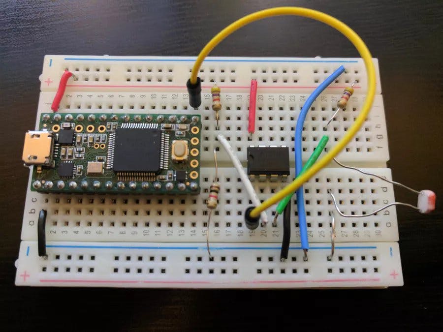
First and foremost, we needed a tachometer that gave us confidence in our speed measurements. The simplest method for us was a light-based tachometer. Initially, we tried to measure analog values, but this proved inaccurate and difficult to control. Instead, we opted to use a digital input. To digitize the photo resistor measurements, we built an op-amp comparator circuit. Mechanical engineering students tend to cringe at the thought of op-amps, but this tutorial explains it very simply and thoroughly.
To build the op-amp comparator circuit, the effective resistance range of the photocell needs to be determined. To do this, test the resistance of the photocell under ambient light conditions and then with your light source shining on it. Note: a laser pointer would be ideal, but a flashlight works well enough.
Resistance When Illuminated
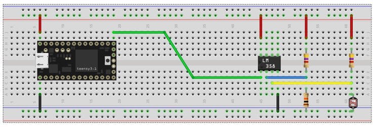
For the comparator circuit, you'll need two voltage dividers. One divider will serve as your reference voltage to the op-amp and the other (with the photocell) will fluctuate around that reference voltage. The range of resistances with the photocell under these conditions is between about 0.5k and 18k. Choose a resistance value somewhere in the middle, say 10k. This will be the value for resistor R3. Resistors R1 and R2 should match. I've chosen 4.7K. To a certain degree, these resistor values are arbitrary, but make sure they match (nominal values) for dependable readings. The voltage output from the photocell voltage divider only needs to alternate between higher and lower than the voltage divider with the two resistors.
Teensy Tachometer Breadboard
Testing and Recording the Output
For this project, I've elected to use a serial monitor to record motor speed values. This way, I can easily collect a history of the data and analyze it later. Using the data from the serial monitor in the Arduino IDE, I've graphed the output in an Excel spreadsheet below. With the code provided, the serial monitor outputs lines in the format "time elapsed~RPM" (where time elapsed is in milliseconds and the tilde is used as a delimiter). The serial monitor screenshot below shows the output of the tachometer (the drops in RPM are due to programmed pauses).
Arduino IDE Serial Monitor
In the graph below, the code on the Arduino Uno with an Adafruit Motorshield v2 (used to control the motor) sped up the motor incrementally until the top speed of the motor was reached. The top speed can be easily visualized in this graph; the speed began to fluctuate wildly above 300 RPM. That value was pretty much expected using this controller-motor combination.
What was not expected was the difference in programmed speeds versus actual output. For instance, I found that when 150 RPM was commanded, the actual output was steady at 98 RPM. For this reason, the tachometer serves as an invaluable diagnostic and debugging tool for the larger project/competition.