This Theremino adapter can be used to replace the parallel port with the USB for input signals up to 5 volts.
Input signals coming from CNC (Travel Fund and emergency switch), must be from 0 to 3.3 Volts. If they are from 0 to 5 Volts then you must put a resistor in series to 100 k (close to the Master). Or reduce the hike with a resistive divider (18k in series and then 10 k to ground). Output signals do not need adapters because they are standard TTL signals (possibly check the CNC can operate with TTL signals (from 0 to 3 Volts).
NOTE: This adapter is used to replace the parallel with the USB, not to operate Mach3 CNC or Linux (unless someone writes about plug-in). We don't write, and because we prefer the simplicity of Theremino CNC, it is because we do not know enough Mach3 and Linux CNC.
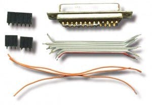
Here you can see the preliminary stages of the construction of the adapter (Click on the images).
Need some wire (small and soft), a DB25 female connector, two small screws, three female connector In step 2.54 (two to three pin and six-pin), a Master module (with firmware version 3.2 or later), and a small plastic box.
The box of these images is a Teko 10011 (dimensions 90 x 56 x 23 mm), You can find it 2 Euro, tax incl, for example, from Webtronic. The venue for the DB25 connector, is a rectangle 41 mm and up 11 mm.
The wires must not be soldered directly onto the Master, but on the female connector. Use only good quality connectors. The connectors are turned and have round holes. Connectors with rectangular holes are not reliable. Don't be fooled by sellers, selling them for Arduino. The strips of connectors with square holes, make contact by a miracle from new. But as time passed they oxidize, lose their elasticity and are no longer reliably contact.
Before you start the wiring, All wires and connectors, must be stripped and tinned with care, with good Tin alloys, containing lead and flux.
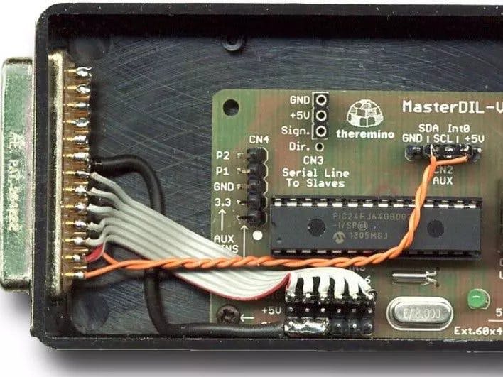
Here is the finished adapter. In this case, In addition to traditional signals to the X axes, Y and Z, have connected two wires (Orange), for the emergency stop button, and to control speed, spindle motor.
These two pictures show the connections (click to enlarge).
Important considerations:
- On The Master, This provision is fixed (not editable by software).
- The corresponding pins of the parallel, range from 2 to 7, and not by 1 to 6, as Master.
A single Master in addition to axes X, Y and Z, can control four other signals with pins 7, 8, 9 and 10. These signals can be generic IN-OUT, or they can control other two stepper motors (that Theremino CNC are called A and B).
Connect the special signals
Special links to the emergency button, the bottom switch, and control the speed of the spindle or Laser power, should be studied from time to time. Follow the links, they were made for Mach3, the list “Ports and Pins” of Mach3, and the documentation of Theremino CNC.
Some hardware stepper motor control, In addition to doing their job natural (control motors), take the trouble to check the condition of the DB25 connector on some wires signals and disables the engines, in case you haven't found them to their liking. Controllers are different from each other and signals that are good for one may not appeal to another.
DB25 connector pins which pay particular attention are: 10, 11, 12, 13 and 15. These pins are commonly used for emergency signals and it will go. If the motors do not move you should link them all five in massa. If that's not enough you should ground also pins 1, 14, 16 and 17.
If the motors do not move, even with all the pins ground control, then you will need to study the pattern and characteristics of motor control hardware. You should also check that the pins of STEP (2, 4, 6 etc…) move really.