Theremino is an Open Source system, to connect computer with the real world.
Theremino is an Open Source system, to connect computer with the real world. Unlike similar systems (for example Arduino), the system works immediately, and does not require any firmware programming. The communication between the PC and the external components is done through "Theremino Master" board which is just an input-output device and not a micro programmable controller as Arduino. You can get the Theremino Master board ready for about twenty dollars (https://www.store-ino.com/) or make it yourself, because the code and instructions for making it are free. You now have more than 150 great Windows applications on the Theremino website(https://www.theremino.com/en/) that allow you to control the components, modules, or sensors connected to the Theremino Master board. The Thermino system uses the power of the PC and the flexibility and low cost of the microcontrollers, so with this combination we can make great devices.
I think the main reason that this system is not very popular with many electronics and do it yourself enthusiasts is this Theremino Master board that usually needs to be ordered and then waited to arrive. However, the developers of Theremino system have made firmware and application (ArduHAL) so that instead of Theremino board, you can use Arduino Nano microcontroller which is often found in do-it-yourselfers. So if we have an Arduino Nano microcontroller we can make a basic Theremino project in less than an hour and we can easily see the benefits. Otherwise, I am sure that after the first projects with the help of Arduino-Teremino Board, you will want to get the original Theremino Board, which is primarily compatible with all projects, has a higher speed of communication and other advantages. The user itself, even without knowing programming, can configure the modules, to measure, physical quantities of all kinds: temperatures, radiations, magnetic fields, earthquakes… and to drive the servos, motors, led lamps, ovens, relè, robots, CNC machines, 3D printers, etc…
This time I will present you two simple examples to control Leds. Let's first explain how to upload the firmware to Arduino nano microcontroller. Let me mention that this procedure is done only once at the beginning and then this Arduino is used for all Teremino projects. I hope most readers already have some experience, so I will explain this step briefly.
Browse to the location of the Arduino library folder. Open the folder “libraries” and copy here the folder “Theremino” which contains the.zip file "ArduinoLibrary_Theremino_V1.8 " that is given below or you can download it from the official site. Now open Arduino IDE software, go to file - examples - Theremino ThereDuino - and click to ThereDuino V1. Now we need to upload given sketch to Arduino Nano board and thats all. Now the Arduino is ready and we can use it in all the supported Theremino projects which are around 100. Next you need to start the "ArduHal" application which is used for mapping and configuring Arduino ports. This application is a link between the Windows software and the microcontroller.
In the first example we will create buttons with which we will turn on and off the LED. For this purpose we use the application "Theremino Buttons". Connect an LED to a digital pin, for example D7 via a 470 ohm series resistor. Now in the ArduHal application we define pin D7 as Digital-out. We launch the Theremino Button application. Now Hold down the CTRL key on the keyboard, and click the left mouse button.
A menu opens where we can change different parameters for this button, and we will just put the name of the button "Led ON", then put slot 7, and finally the maximum value which in this case is 1000. We do the same with the second button, but for the name we put "Led OFF" and value 0. Now with this application we can turn on and off Led through the PC software that we modified ourselves.
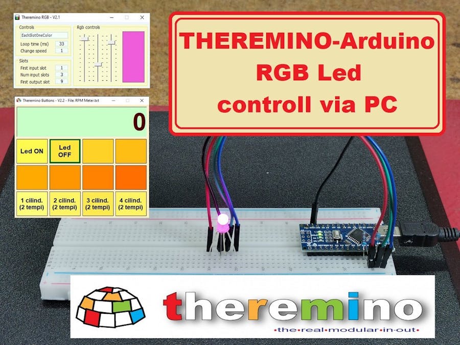
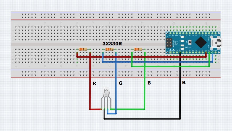
The next example is control of RGB Led. For this purpose, we connect the RGB LED diodes to the D9, D10, and D11 pins through the appropriate series resistors as shown in the diagram. Then we start the ArduHal application and set these three pins as PWM_8. This way we can continuously change each color. Now launch the Theremino RGB application and set First input slot - 1, Num input slots - 3 and First output slot - 9. When dragging the sliders up and down, the intensity of each color changes continuously. By combining these three basic colors we can generate the whole spectrum. The program also has options to change the intensity of the three colors automatically according to certain mathematical functions, and we can also change the time and speed.
Finally, this is just a small introduction to the world of Theremino system and I recommend you to go to their website(https://www.theremino.com/en/), where you will find a lot of information, and each project is explained and documented in the smallest detail. And best of all, many great apps are free. In the future I will present you many more projects, both with Arduino Nano and the original Theremino master board.