Ultrasonic Sensor HC-SR04 Interfacing with Arduino
The HC-SR04 is a widely used ultrasonic distance sensor for Arduino and embedded electronics projects. It provides a simple non-contact method for determining the distance between the sensor and an object. The module works by transmitting ultrasonic sound waves and measuring the time required for the reflected signal to return to the receiver. The HC-SR04 typically operates at 40 kHz and can measure distances from approximately 3 cm to 300 cm, making it suitable for applications such as obstacle-avoiding robots, object detection, parking assistance, security systems, proximity sensing, and liquid-level monitoring.
In this tutorial, we will understand the operating principle of the HC-SR04, examine its pin configuration and specifications, and learn how it can be connected to an Arduino Uno for distance measurement. The measured distance can also be displayed on a 16×2 alphanumeric LCD.
What is the HC-SR04 Ultrasonic Sensor?
The HC-SR04 is an ultrasonic ranging module that uses sound waves to determine the distance to an object. It operates using two ultrasonic transducers mounted on the module. One transducer acts as the transmitter and generates the ultrasonic signal, while the other works as the receiver and detects the reflected signal.
Ultrasonic sound refers to sound waves with frequencies above approximately 20 kHz, which is beyond the normal range of human hearing. The HC-SR04 uses a frequency of approximately 40 kHz for distance measurement. When the module is triggered, it transmits an ultrasonic burst toward the surrounding area. If an object is present in the path of the sound waves, the waves are reflected back toward the sensor. The module detects this reflected signal and provides a timing pulse that can be measured by a microcontroller.
The HC-SR04 contains the ultrasonic transmitter and receiver along with the control circuitry required to generate the ultrasonic signal and process the returning echo. Because the module requires only power, trigger, and echo connections, it can be easily interfaced with development boards such as the Arduino Uno.
Features and Specifications of HC-SR04
One of the main advantages of the HC-SR04 is its relatively wide measurement range. The module can detect objects from approximately 3 cm up to 300 cm away from the sensor. It provides a resolution of about 0.3 cm, while the commonly specified accuracy is approximately 3 mm.
The sensor operates from a 5V DC supply and has a typical operating current of around 15 mA. Its ultrasonic operating frequency is 40 kHz and its measuring angle is less than 15 degrees. The compact module has dimensions of approximately 45 × 20 × 15 mm, making it convenient for use in breadboard experiments, robotic platforms, automation systems, and other embedded projects.
The non-contact nature of ultrasonic measurement is particularly useful when the object being measured should not be physically touched. For example, the HC-SR04 can be mounted on a robot to detect obstacles or positioned above a tank to estimate the level of liquid.
HC-SR04 Ultrasonic Sensor Pinout
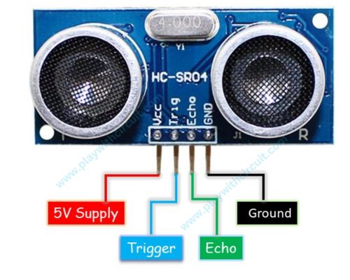
The HC-SR04 has four pins: VCC, Trig, Echo, and GND. The VCC pin is the power supply input and should be connected to the 5V supply of the Arduino Uno. The Trig pin is the input used to initiate a distance measurement. The Arduino starts a measurement by applying a HIGH pulse of approximately 10 microseconds to this pin.
The Echo pin is the output from the HC-SR04. After the ultrasonic pulse is transmitted, the sensor generates a pulse on the Echo pin whose duration corresponds to the time taken by the ultrasonic wave to travel to the object and return to the receiver. The Arduino measures this pulse width and uses it to calculate the distance.
The GND pin is connected to the ground of the Arduino. A common ground between the Arduino and HC-SR04 is required for proper operation.
How Does the HC-SR04 Work?
The HC-SR04 works using the principle of ultrasonic echolocation. The sensor sends a burst of high-frequency sound waves and measures the time required for the reflected waves to return. Since the speed of sound through air is known approximately, the measured travel time can be converted into distance.
A measurement starts when the Arduino sends a HIGH pulse of approximately 10 µs to the Trig pin. The HC-SR04 responds by transmitting a burst of 40 kHz ultrasonic waves through its transmitter. These waves travel through the air and are reflected when they encounter an object.
When the reflected ultrasonic signal reaches the receiver, the HC-SR04 processes the signal and generates an Echo pulse. The width of this pulse represents the total time taken by the ultrasonic wave to travel from the sensor to the object and back to the sensor.
The Arduino measures the duration of the Echo pulse and calculates the distance using the relationship between distance, time, and the speed of sound. The basic formula is Distance = (Time × Speed of Sound) / 2. The division by two is necessary because the measured time represents the complete round trip of the ultrasonic signal.
At room temperature, the speed of sound is approximately 343 metres per second, which is about 0.034 cm per microsecond. Therefore, the distance can also be approximated using the formula Distance in centimetres = Echo pulse time in microseconds / 58.309.
For example, if the Echo pulse has a duration of 1000 µs, the distance can be calculated as follows: Distance = (0.034 × 1000) / 2, which gives approximately 17 cm. Therefore, an Echo pulse width of 1000 µs indicates that the reflecting object is approximately 17 cm away from the sensor.
Applications of the HC-SR04
The HC-SR04 can be used in many electronics and embedded applications where non-contact distance or object detection is required. One of its most common applications is distance measurement, where the sensor determines the distance between itself and a nearby object.
In robotics, the HC-SR04 is frequently used for obstacle detection and obstacle avoidance. A robot can monitor the distance in front of it and take appropriate action when an obstacle is detected within a predefined range. Multiple sensors can also be used when distance information from different directions is required.
The sensor can also be used for object detection in automation and security projects. By continuously monitoring the Echo signal, a microcontroller can determine whether an object has entered a particular detection area.
Another common application is liquid-level measurement. When installed above a container, the HC-SR04 can measure the distance between the sensor and the liquid surface. This measured distance can then be used to determine the approximate level of the liquid inside the container.
The HC-SR04 is also useful in parking assistance systems for detecting the distance between a vehicle and an obstacle. Other applications include proximity sensing, smart home systems, interactive electronics projects, and educational robotics.
Interfacing HC-SR04 with Arduino Uno
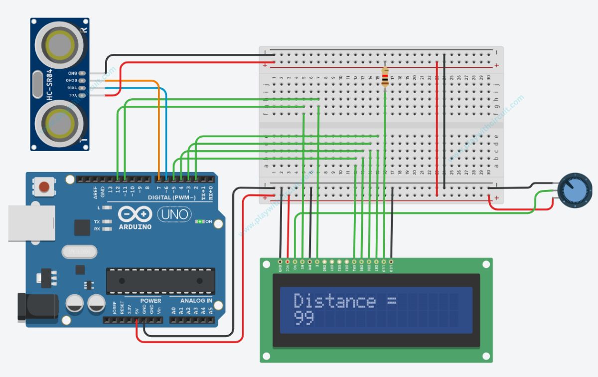
The HC-SR04 can be connected to an Arduino Uno to create a simple distance-measurement system. In this setup, the Arduino generates the trigger signal, measures the Echo pulse, calculates the distance, and displays the result on a 16×2 alphanumeric LCD.
The hardware required for this project includes an Arduino Uno Rev3, one HC-SR04 ultrasonic distance sensor, a 16×2 LCD, a 10 kΩ potentiometer, a 1 kΩ resistor, a full-size breadboard, connecting wires, a USB A/B cable for programming the Arduino Uno, and a 12V supply adapter for providing power to the Arduino.
The VCC pin of the HC-SR04 is connected to the 5V DC supply of the Arduino. The Trig pin of the sensor is connected to digital pin 6 of the Arduino Uno. This pin acts as an output from the Arduino and provides the trigger signal to the sensor. The Echo pin is connected to digital pin 7 of the Arduino. This pin acts as an input to the Arduino because the HC-SR04 generates the Echo pulse on this connection. Finally, the GND pin of the sensor is connected to the Arduino ground.
The 16×2 LCD is connected to the Arduino as follows. The VSS pin, which is pin 1 of the LCD, is connected to GND, while VDD pin 2 is connected to VCC. The VEE pin 3 is connected to the variable pin of a 10 kΩ potentiometer, which is used to adjust the LCD contrast. The RS pin 4 is connected to Arduino pin 12, and the R/W pin 5 is connected to GND. The Enable pin, E or pin 6, is connected to Arduino pin 11.
The LCD data pins D0, D1, D2, and D3, corresponding to pins 7, 8, 9, and 10 of the LCD, are connected to GND. The higher data pins are used for communication with the Arduino. LCD pin D4, which is pin 11, is connected to Arduino pin 5. D5, or LCD pin 12, is connected to Arduino pin 4. D6, or LCD pin 13, is connected to Arduino pin 3. D7, or LCD pin 14, is connected to Arduino pin 2.
The LCD backlight connections are also required. LED(+) or LCD pin 15 is connected to VCC through a 1 kΩ resistor, while LED(-), which is pin 16, is connected to GND. The potentiometer allows the LCD contrast to be adjusted so that the displayed distance can be clearly viewed.
Software Requirements
The project can be developed using Arduino IDE version 2.1.1 or later. The LiquidCrystal library is required for controlling the 16×2 LCD. The NewPing library by Tim Eckel can also be used to simplify communication with the HC-SR04 and distance measurement.
To install the NewPing library, open the Arduino IDE and navigate to Sketch, followed by Include Library and Manage Libraries. Alternatively, the Library Manager can be opened using the Ctrl + Shift + I shortcut. Search for NewPing in the library search field, locate NewPing by Tim Eckel, and install the latest available version.
The NewPing library provides functions that simplify the process of triggering the ultrasonic sensor and obtaining a distance measurement. Although a library can handle the measurement process, understanding the trigger, Echo pulse, and time-of-flight calculation is useful when developing ultrasonic sensing applications.
Understanding HC-SR04 Measurement Accuracy
Although the HC-SR04 is simple to use, the stability of its readings can depend on the target and the surrounding environment. The sensor determines distance based on the reflected ultrasonic signal, so the characteristics and orientation of the object can influence the quality of the measurement.
Large and relatively flat surfaces generally provide a stronger reflection, while objects with irregular, angled, or sound-absorbing surfaces can produce weaker or less consistent echoes. The specified measuring angle of the HC-SR04 is less than 15 degrees, so the sensor should ideally be positioned directly toward the target.
The sensor should also have a clear path between the transmitter, the target, and the receiver. Objects located within the measurement path can produce unexpected reflections and affect the calculated distance. Environmental conditions can also influence the speed of sound. The commonly used value of 343 m/s assumes approximately room-temperature conditions.
Conclusion
The HC-SR04 is a practical and inexpensive ultrasonic sensor for learning and implementing distance measurement with Arduino. It uses a simple time-of-flight technique in which the Arduino triggers an ultrasonic pulse, measures the duration of the returning Echo signal, and converts that timing information into distance.
With its 3 cm to 300 cm measurement range, 40 kHz operating frequency, 5V operation, and four-pin interface, the HC-SR04 can be easily integrated into robotics, automation, object detection, parking assistance, proximity sensing, and liquid-level monitoring projects.
Connecting the HC-SR04 to an Arduino Uno requires only the VCC, Trig, Echo, and GND connections. Adding a 16×2 LCD allows the calculated distance to be displayed directly, making this a useful project for understanding both ultrasonic sensing and basic Arduino interfacing.