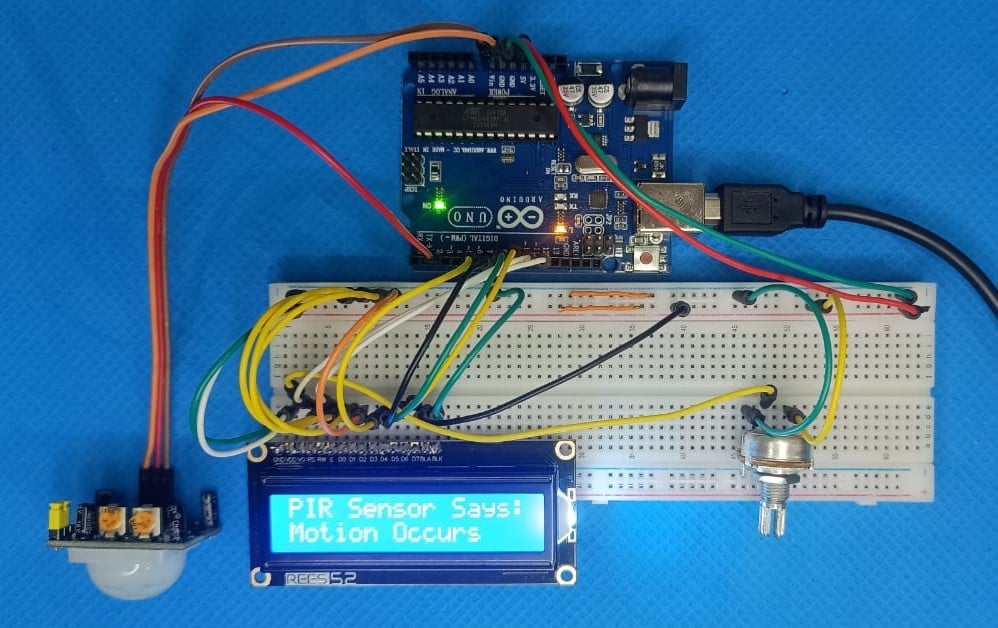
Motion detection is a common requirement in electronics projects. From automatic lighting and security systems to smart-home devices and occupancy detection, a circuit often needs a simple way to determine whether someone has moved through a particular area. A PIR, or Passive Infrared, sensor is one of the simplest ways to add this capability to a microcontroller-based project.
The HC-SR501 is a popular PIR motion sensor module that can detect movement by sensing changes in infrared radiation. Unlike an active sensor that transmits energy and measures a reflected signal, the HC-SR501 passively monitors infrared energy already present in its surroundings. This makes it inexpensive, simple to interface, and useful for a wide range of maker and embedded electronics projects.
In this article, we will look at how the HC-SR501 detects motion, how its pyroelectric sensing element and Fresnel lens work, the purpose of the different components on the module, its operating modes and adjustments, and how the sensor can be connected to an Arduino UNO.
How Does a PIR Motion Sensor Work?
A PIR sensor detects changes in infrared radiation rather than measuring visible light. Every object with a temperature above absolute zero emits some infrared radiation, and the human body continuously emits infrared energy because of its body temperature. The PIR sensor detects changes in this radiation when a person or another warm object moves through its detection area.
The sensor itself does not transmit infrared energy. Instead, it monitors the infrared radiation arriving from the surrounding environment. When the radiation pattern changes, the sensing element produces an electrical signal that can be processed by the electronics on the module.
Two major parts are responsible for the optical and sensing operation of a typical PIR module: the pyroelectric sensor and the Fresnel lens.
Pyroelectric Sensor
The pyroelectric element is the actual sensing component that responds to changes in infrared radiation. It contains a pyroelectric material that generates an electrical charge when the infrared energy reaching it changes. The sensing element has two infrared-sensitive sections. These sections are arranged so that changes affecting both sides equally tend to cancel each other, while a difference between the two sections produces a useful signal.
When there is no movement in front of the sensor, both sections receive approximately the same amount of infrared radiation. As a result, their differential output remains close to zero. When a person moves across the detection area, one section of the sensor is affected before the other. This creates a differential change in the electrical signal. As the person continues moving and reaches the second section, the signal changes in the opposite direction. The module's electronics use these changes to determine that motion has occurred.
This is why a PIR sensor is primarily a motion detector rather than a conventional temperature sensor. It is the change in infrared radiation across the sensing elements that produces the detection signal.
Fresnel Lens
The white dome covering the HC-SR501 is a Fresnel lens. Instead of using a conventional curved lens, a Fresnel lens uses a series of concentric grooves that bend and focus incoming radiation.
In the PIR module, the Fresnel lens directs infrared radiation toward the pyroelectric sensing element. It also creates a wider field of view by dividing the detection area into multiple zones.
As a warm object such as a person moves through these zones, the amount of infrared radiation reaching different parts of the sensing element changes. This produces the differential signal required for motion detection.
The Fresnel lens also allows the optical system to remain relatively compact while providing a broad detection area.
HC-SR501 Pinout
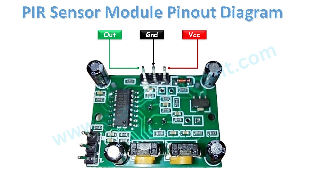
The HC-SR501 has three main electrical connections: VCC, GND, and OUT.
VCC is the power input for the module. The module can generally be powered from approximately 4.5 V to 12 V, and 5 V is commonly used when connecting it to an Arduino UNO.
GND is the ground connection and should be connected to the ground of the power supply and the microcontroller.
OUT is the digital motion-detection output. When no motion is detected, the output remains LOW. When the sensor detects movement, the output changes to HIGH, typically around 3.3 V.
For an Arduino UNO, the basic connections are:
HC-SR501Arduino UNOVCC5VGNDGNDOUTDigital Pin 2
This simple three-wire connection is one of the main reasons the HC-SR501 is convenient for prototyping.
Understanding the HC-SR501 Module Hardware
Although the HC-SR501 appears to be a simple sensor board, several components on the module are responsible for signal processing, protection, and configuration.
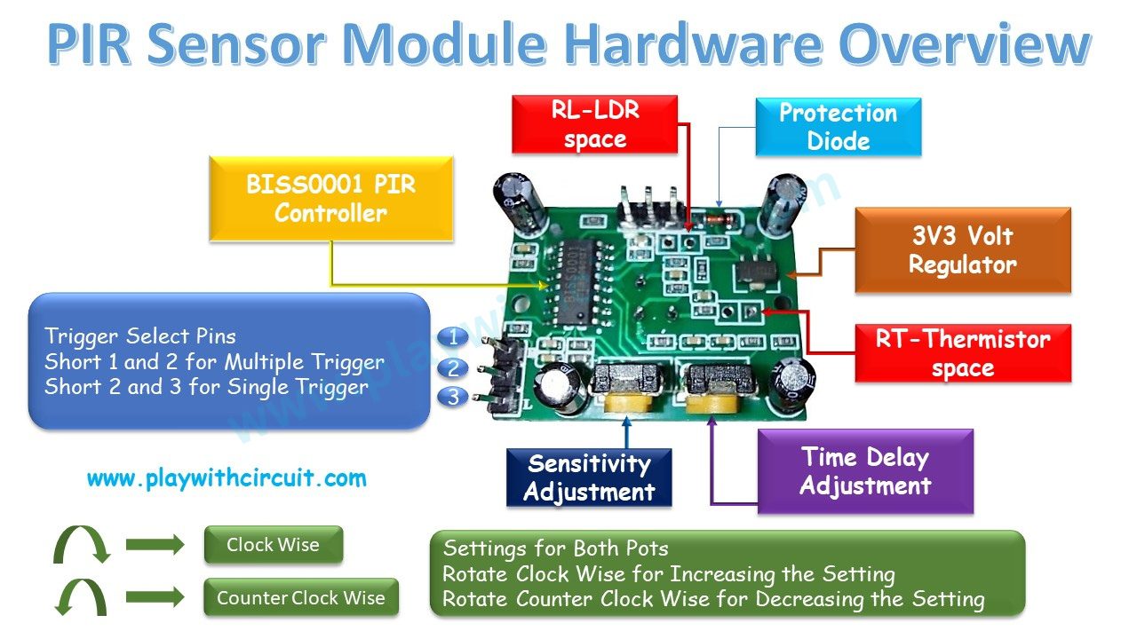
BISS0001 PIR Controller
The BISS0001 IC is used for PIR signal processing. The electrical signal generated by the pyroelectric element is relatively small and requires processing before it can be used as a digital motion signal.
The controller amplifies and processes the sensor signal while also helping filter unwanted noise and interference. Its output is then used to drive the module's OUT pin.
RT and RL Connections
The HC-SR501 also provides RT and RL positions on the back of the PCB for additional components.
RL can be used for an LDR or photoresistor. This can be useful when the sensor needs to respond differently depending on the surrounding light conditions, such as applications intended to operate primarily in darkness.
RT can be used with a thermistor or another temperature-sensitive resistor. This allows the sensor to be adapted for environments where temperature variations can affect motion detection.
Protection Diode
A protection diode is included on the module to help protect the circuit against reverse-voltage conditions.
This is particularly useful during prototyping, where power connections may be changed frequently.
3.3 V Voltage Regulator
The module also contains a 3.3 V voltage regulator. This allows the sensor circuitry to operate from the module's higher input supply range.
Because of this regulator, the HC-SR501 can be powered from an input in the approximate 4.5 V to 12 V range while maintaining the appropriate internal supply voltage for its sensing and processing circuitry.
HC-SR501 Trigger Modes
One of the useful features of the HC-SR501 is the ability to select between two trigger modes using the onboard jumper.
These modes are generally referred to as single trigger and multiple trigger modes.
Single Trigger Mode
In single trigger mode, the OUT pin becomes HIGH when motion is detected and remains HIGH for the selected delay period.
If another motion event occurs while the output is already HIGH, that additional event is ignored. The sensor waits for the current output pulse to finish before it can generate another trigger.
This mode is useful when each detection should produce a separate pulse and repeated movement during that pulse should not continuously extend the output.
Multiple Trigger Mode
In multiple trigger mode, the sensor can respond to additional movement while the OUT signal is already HIGH.
When another movement event is detected during the active period, the timing is reset or extended. As a result, the output can remain HIGH for longer when movement continues to occur.
This behavior can be useful for applications such as automatic lighting, where continued movement should keep the system active rather than allowing the output to turn off while someone is still in the monitored area.
Adjusting the Detection Sensitivity
The HC-SR501 has a potentiometer that controls its sensitivity. This allows the detection range to be adjusted according to the application.
The typical adjustable range is approximately 3 m to 7 m. Turning the sensitivity control clockwise increases the sensitivity, while turning it counterclockwise decreases it.
The actual detection range can vary depending on environmental conditions, installation height, the temperature difference between the target and its surroundings, and the direction in which the target moves.
For this reason, the sensitivity should be adjusted while the sensor is installed in its actual operating position.
Adjusting the Time Delay
The second potentiometer controls how long the OUT pin remains HIGH after motion is detected.
Turning the potentiometer clockwise increases the delay, while turning it counterclockwise decreases the delay.
This adjustment is useful when the HC-SR501 is being used to control another circuit. For example, a longer delay may be appropriate for an automatic light, while a shorter delay may be sufficient when the output is being used simply as a motion event signal for a microcontroller.
Using the HC-SR501 Without a Microcontroller
The HC-SR501 does not always need an Arduino or another microcontroller. Since the module already processes the pyroelectric signal and provides a digital output, its OUT signal can be used to control another circuit through suitable interface circuitry.
For example, an LED can be connected to the output as a simple motion indicator. The sensor is powered through its VCC and GND pins, while the LED is connected to the OUT pin through a suitable current-limiting resistor.
When motion is detected, the OUT pin goes HIGH and the LED turns on.
This type of standalone configuration is also useful when initially testing the sensor. The sensitivity, delay, and trigger settings can be adjusted without involving any software.
One important point during testing is that the PIR module needs some time to stabilize after power-up. The sensor should be allowed to adjust to the infrared conditions of its surroundings before evaluating its detection behavior.
Connecting the HC-SR501 to Arduino UNO
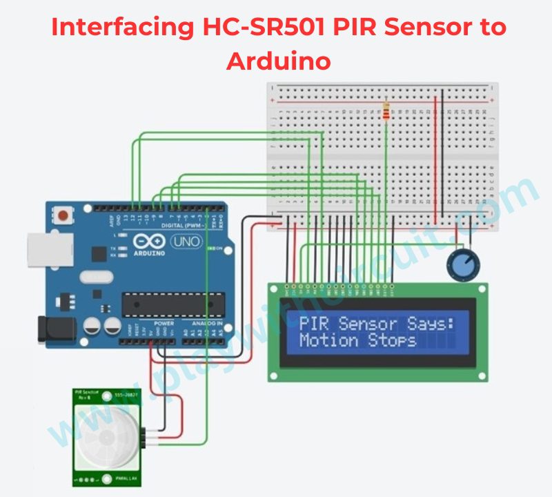
The HC-SR501 can be connected directly to an Arduino UNO because its output is already available as a digital signal.
In a typical Arduino setup, the PIR sensor is powered from the Arduino's 5 V and GND pins, and the OUT pin is connected to digital pin 2.
A 16×2 LCD can also be added to display the detected motion status. The LCD can be operated in 4-bit mode, which reduces the number of Arduino pins needed for communication.
The LCD's RS pin is connected to Arduino pin 12 and its Enable pin is connected to pin 11. The data pins D4 through D7 are connected to Arduino pins 6, 7, 8, and 9.
A 10 kΩ potentiometer is connected to the LCD's VEE/Vo pin for contrast adjustment. A 220 Ω resistor is used with the LCD backlight to limit current.
Applications of the HC-SR501
The simple interface and adjustable operating parameters make the HC-SR501 useful in a variety of electronics projects. Typical applications include automatic lighting, security alarms, room occupancy detection, smart-home systems, interactive installations, and motion-triggered devices.
For example, an Arduino can monitor the sensor output and activate a light when movement is detected. The same digital signal can also be used as an input for a larger automation system.
For open-hardware projects, the module is particularly convenient because the complex analog sensing and signal-conditioning stages are already integrated into the board. The designer can therefore focus on how the motion event should be used rather than having to design the complete PIR front-end circuit.
Conclusion
The HC-SR501 provides a straightforward way to add passive infrared motion detection to an electronics project. Its pyroelectric sensing element detects changes in infrared radiation, while the Fresnel lens provides a broad detection area and directs infrared energy toward the sensing element.
The onboard BISS0001 controller processes the sensor signal and produces a digital output, allowing the module to be connected directly to an Arduino UNO or another microcontroller. Its adjustable sensitivity, time delay, and selectable trigger modes also give the designer control over how the sensor responds to movement.
With only three primary connections—VCC, GND, and OUT—the HC-SR501 is easy to integrate into prototypes and open-hardware designs. It can also operate as a standalone motion detector when a microcontroller is not required.
For additional technical details and the original Arduino implementation, visit the Play with Circuit reference: How HC-SR501 PIR Sensor Works & How to Interface It with Arduino.