Hi Everyone, This is my 1st Arduino's tutorial video. In this video i am going to show you how to use a LDR or Light Dependent resistor to turn on and off another circuit or a LED.
Wouldn’t it be really cool if whenever a room gets dark, a light bulb automatically turns ON and eliminates the darkness? In this very simple project, I am focusing on eliminating darkness. You can even use this as an emergency lighting system.
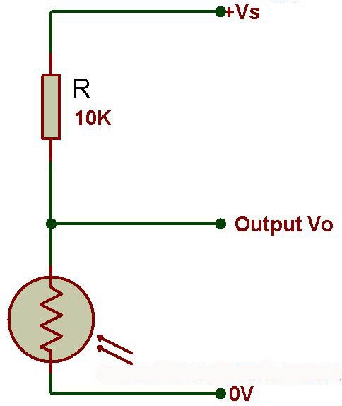
The LDR is a special type of resistor which allows a lower voltage to pass through it (high resistance) whenever its dark and higher voltages to pass (low resistance) whenever there is a high intensity of light.
We are going to use a 10k resistor along with the LDR to create a voltage divider circuit. The varying resistance of the LDR is converted to a varying voltage that the analog pin of the Arduino will then be using in its logic.
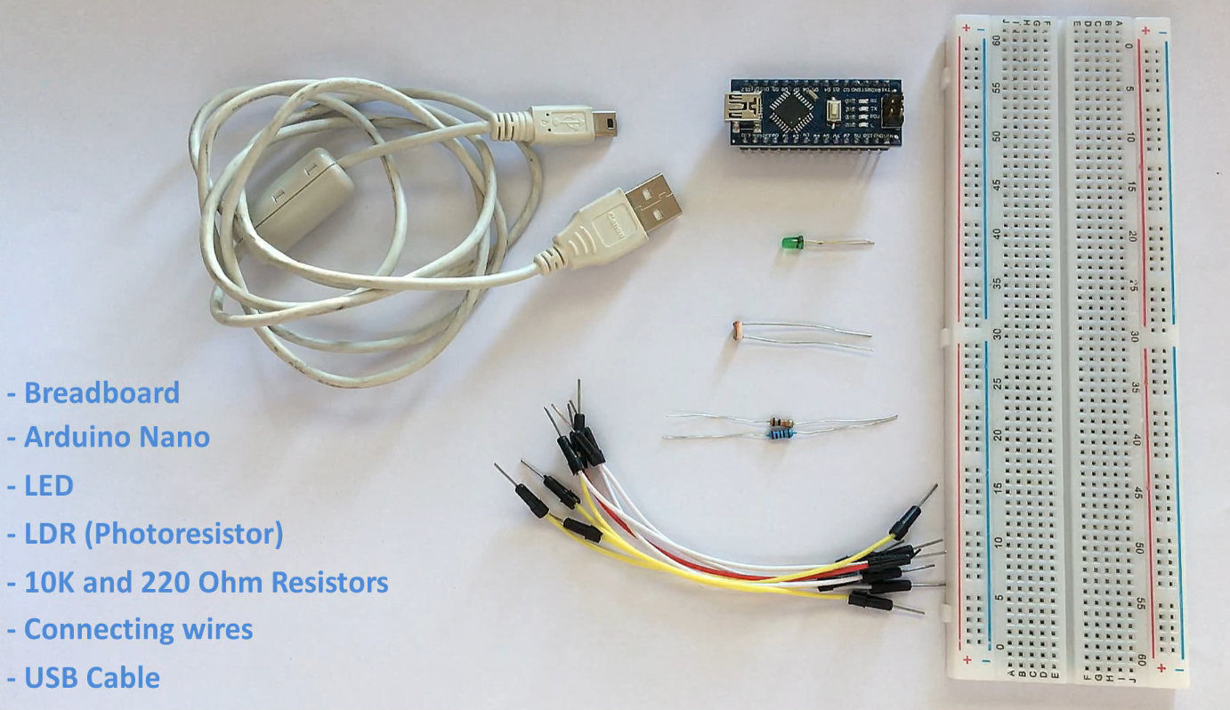
For this very simple DIY Arduino project we need:
- a breadboard
- an arduino uno/nano (whatever is handy)
- LED (Light Emitting Diode)
- LDR (Photoresistor)
- A 10K Resistor for creating the voltage divider and a 220ohm resistor for the LED
- Few breadboard friendly connecting wires
- and a USB cable to upload the code to the Arduino
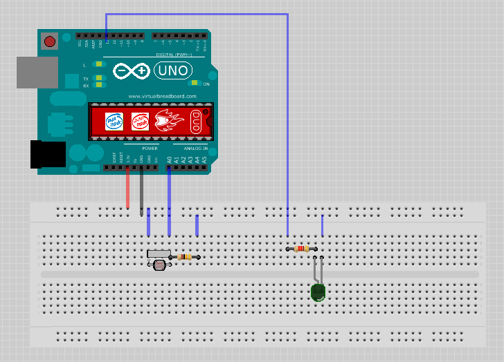
- Connect the 3.3v output of the Arduino to the positive rail of the breadboard
- Connect the ground to the negative rail of the breadboard
- Place the LDR on the breadboard
- Attach the 10K resistor to one of the legs of the LDR
- Connect the A0 pin of the Arduino to the same column where the LDR and resistor is connected (Since the LDR gives out an analog voltage, it is connected to the analog input pin on the Arduino. The Arduino, with its built-in ADC (Analog to Digital Converter), then converts the analog voltage from 0-5V into a digital value in the range of 0-1023). - Now connect the other end of the 10K resistor to the negative rail - And the the second (free) leg of the LDR to the positive rail
Pretty much this is what we need for the light sensing. Basic circuits like this can be done without an Arduino aswell. However, if you want to log the values and use it to create charts, run other logics etc. I will recomend an Arduino or ESP8266 or may be a ESP32 for this.
Now, as we want our circuit to do something in the real world other than just displaying the values on the computer screen we will be attaching a LED to the circuit. The LED will turn on when its dark and will go off when its bright. To achieve this we will:
- Place the LED on the breadboard
- Connect the 220ohm resistor to the long leg (+ve) of the LED
- Then we will connect the other leg of the resistor to pin number 13 (digital pin) of the Arduino
- and the shorter leg of the LED to the negative rail of the breadboard
const int ledPin = 13;
const int ldrPin = A0;

void setup() {
Serial.begin(9600);
pinMode(ledPin, OUTPUT);
pinMode(ldrPin, INPUT);
}

void loop() {
int ldrStatus = analogRead(ldrPin);
if (ldrStatus <= 200) {
digitalWrite(ledPin, HIGH);
Serial.print("Its DARK, Turn on the LED : ");
Serial.println(ldrStatus);
} else {
digitalWrite(ledPin, LOW);
Serial.print("Its BRIGHT, Turn off the LED : ");
Serial.println(ldrStatus);
}
}