Learn motor basics and how they can be automated using Arduino to read the PWM signals directly from a receiver.
Radio control (RC) electronics are cheap and commonplace. You can control a mobile robot from hundreds of feet (if not miles) away with standard hobby radios. On top of that, this control comes with hardly any latency and modern automatic frequency hopping digital radios practically guarantee no interference.
Taking advantage of these benefits is easy using just a receiver, a few servos, and electronic speed controllers (ESCs) with motors.
However, if you want to be able to hand over autonomous control to an Arduino it can feel intimidating. Not to worry, you have probably already used standard radio control pulse width modulation (PWM) without even realizing it! From there, reading the signals from a receiver isn’t much harder.
RC Hardware: Servos, Motors, Controllers
The most commonplace of radio control devices for us makers who are familiar with Arduino is the lowly servo. However, much more can be accomplished with brushed or brushless motors and their accompanying ESCs.
Servo Motors
Servos are basically geared motors with a built-in PID control board and potentiometer to sense position. Kind of like a motor, ESC, and feedback all in one!
Their limitation, however, is that they are very slow to rotate and generally have 270-degree limits to their rotation. Some fancy servos are multiturn, but generally, they still only turn up to a set number of times in one direction or the other. Most servos take five or six volts but some will take up to 7.4, and others much higher directly from a battery pack.
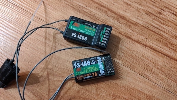
Receivers
Receivers (RX) are able to send signals to control servos and ESCs but don’t have the ‘brains’ of an Arduino.
A common six-channel receiver.
They take in a channel position and output that as a PWM signal with a pulse width of between 500 and 2500 microseconds, though typically in a range of just 1000-2000us. This is what the Arduino does to control a servo! All the way clockwise is 500 or so, and 2500 is all the way counterclockwise. ESCs use this in a similar way (more on that later).
Side note: With a standard receiver, usually the 1000-2000 range is used, meaning a 270-degree servo may only rotate shy of 180 degrees from a receiver. One use of an Arduino here is to map that 1000-2000 range to a 500-2500 value to get that extra range back.
Transmitters
Transmitters (TX) are typically sold paired with a receiver, though a same-brand receiver of another model may work.
The number of channels controllable is typically limited by the number of inputs. The transmitter may have joysticks, dials, or switches mapped to receiver channels. Fancy ones are digital and have a display allowing you to create custom throttle curves and mixes. This is useful for driving a robot with one stick controlling two motors, allowing you to use the other stick for a gripper or arm, you could use a switch to activate or deactivate autonomy via an Arduino, etc.
Brushed Motors and ESCs
Brushed motors are likely what you are familiar with from Arduino robotics projects. They have a grey steel cylindrical can that is often round or with two flat faces for smaller motors. They can run forward or backward by reversing voltage to them. When a voltage is applied, they run as fast as they can for that voltage in the direction that current flow dictates.
Brushed ESCs pulse power to the motor to vary its speed, but each pulse is full battery voltage which preserves the motor torque much better than an analog voltage sweep control would. However, it is true that at 50% throttle the motor will receive a 50% duty cycle meaning on average half the battery voltage. These are ‘dumb’ motors with no feedback so the ESC doesn’t do anything to compensate for the motor loading or current speed.
Brushed ESCs like the Hobbywing Quicrun will handle practically any 12V or less system for just over $20, and there are much smaller lower power options available too if you aren’t drawing 30 amps per motor and using a three-cell LiPo. Brushed ESCs have a large market gap in the 12V-24V range but are prolific in the sub-12V area. That said, you can get an electric scooter or golf cart motor controller that will run voltages above 72V and over 500A, or as low as 36V and 100A, though these are massive, bulky, and much less hacker-friendly than the hobby counterparts.
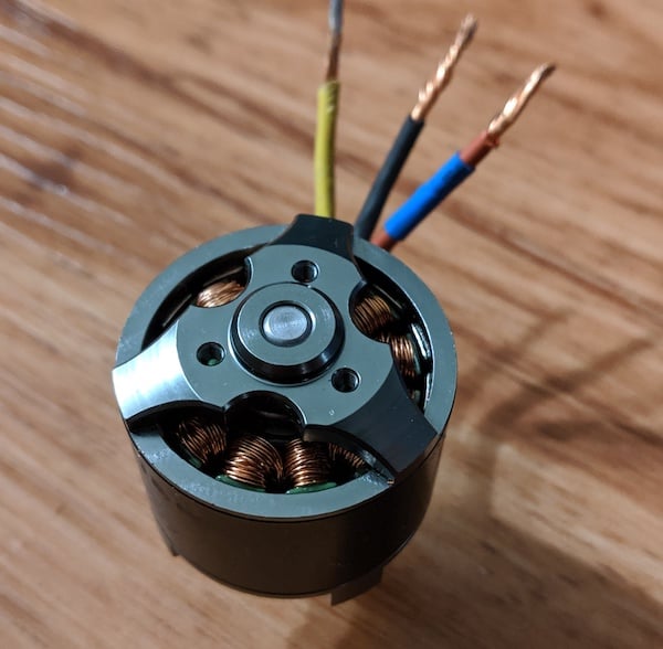
Brushless Motors (BLDC) and ESCs
Due to the advent of racing drones and camera drones, brushless hobby motors and ESCs are cheaper than ever.
Brushless DC motors use three phases of sine wave AC created via the ESC from a DC power source. As the motor turns, magnets move past sets of three coils whose electrical pulses are carefully and perfectly timed and sequenced by the ESC with the use of the motor’s back-EMF to determine its speed and position.
For high speeds this functionality is great. But at low speeds, you may have issues since the back-EMF is only generated after the motor is in motion. This is why larger motors, like the ones found in electric skateboards, are usually sensored. These sensored motors have Hall effect sensors to ensure the ESC knows the exact motor position when starting up. This allows for far improved low-end torque but usually requires a VESC or similarly expensive ESC pairing ($75+).
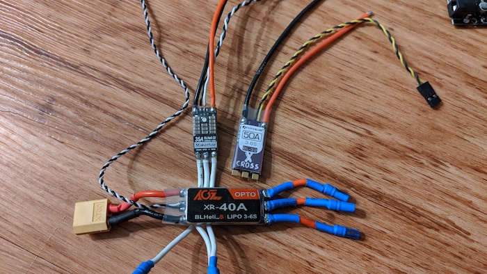
A variety of 35A brushless ESCs capable of running at up to 24V are available for under $20 on Amazon. A similar voltage and power ESC for a brushed motor would likely cost twice that. Most of these motors and ESCs are designed for RC planes and drones and as such are meant to be used with high airflow cooling them, thus they seem impossibly small for their power ratings and are incredibly power-dense and lightweight.
Brushless motors usually have a power/weight ratio of four to ten times that of a brushed equivalent. This does have a downside, however: that propeller airflow is usually unavailable on the ground and you may need a fan to cool your ESCs. Also, since propellers typically only turn way only, reversing these motors may be a challenge despite the ESCs being fully capable hardware-wise.
Note: Blheli_32 is a firmware advertised on many drone ESCs. This type of ESC can be paired with a cheap $10-20 USB linker to give you immense control over the performance characteristics of the motor, including the ability to reverse (3D mode) and startup current limiting to prevent blowing up the ESC. Without this type of ESC, hardly any sensorless ESCs will allow you to reverse the motor.
How to Use PWM With an Arduino
Servos and Simple Devices
Like I said before you have likely used PWM with an Arduino already. The built-in servo command is basically the same as a receiver output, but it takes a Servo.write() argument from 0-180 as if that were a servo angle.
You can easily change and expand this range by using Servo.writeMicroseconds() instead, which allows actual microsecond values, giving you full control. This will let you expand the range of your servos using values of 500-2500 (you may need to test all values to see which the servo actually responds to, the upper and lower bounds vary).
All About Arming (Or: Help! My ESC doesn’t work!)
If you have ever tried using an ESC by writing values to it right away you might see that it doesn’t do anything. Brushed and brushless hobby ESCs are all designed to go into RC vehicles, and an ESC that instantly turns on the moment it gets power would cause the vehicle to freak out and move unpredictably.
This is why nearly all ESCs require arming: a specific PWM signal held for a short while will usually cause an audible beep and/or LED flash indicating the ESC has armed, and then it will work as expected unless you send a signal out of the range of the ESC’s expected limits.
Usually, this arming will be at 1000us for brushless single-direction ESCs, or 1500us for brushed reversing ESCs. This would be the throttle position for the motor to be stopped. Values of 1500 >> 1000 run the reversible motors backward at increasing speeds, while 1500 >> 2000 run them forward at increasing speeds. For single direction ESCs, the motor is stopped at 1000 and speeds up as you approach 2000.
Note: The values 1000, 1500, and 2000 are all guesses. As with servos, the exact values may be different. In my experience, going up above the expected range for some ESCs might let them continue at max speed. For others, they will think the receiver disconnected and need to be rearmed, and the motor will stop. The best way to reliably test the acceptable range is with a sweeping for loop that checks every 10us for 50ms each, Then note the min and max, and use those in variables to adjust your ranges for your code.
Reading Receiver Values With pulsein()
Pretty much all you need to do to read values from a receiver is connect any GND pin to the receiver ground and connect the receiver signal pin to any Arduino digital pin. Then set that pin as an input and use the pulsein command. pulseIn(pinNum, HIGH) should work great.
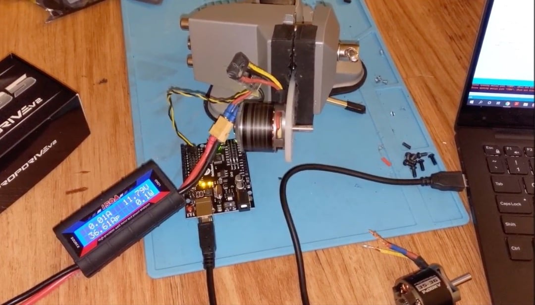
Now that we've covered how Arduino can control these different motors, check out the video to see how to use Arduino for PWM motor control and radio communication.