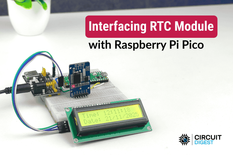
Build an accurate Raspberry Pi Pico real-time clock using the DS3231 RTC module and I²C LCD in minutes — ideal for automation and time-based projects.
Reliable timekeeping is essential for many embedded projects — from automated alarms to data loggers. In this hands-on tutorial, you’ll learn how to interface a Raspberry Pi Pico RTC Module using the I²C protocol and display the output on a 16×2 I²C LCD screen — all programmed using the Arduino IDE.
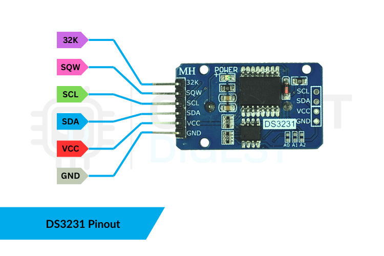
Why Use a DS3231 RTC Module?
The DS3231 is one of the most accurate RTC modules available for makers today. Unlike older clocks that drift over time due to temperature fluctuations, the DS3231 includes a Temperature-Compensated Crystal Oscillator (TCXO) that constantly corrects time based on temperature changes, ensuring high precision in a range of environments.
It tracks seconds, minutes, hours, date, month, and year — and even handles leap years automatically. It also has a battery backup (typically a CR2032 coin cell), so your Pico project keeps time even when power is disconnected.
What You’ll Build
With this guide, you’ll:
- Connect a DS3231 RTC module and a 16×2 I²C LCD to the Raspberry Pi Pico using I²C communication.
- Write Arduino code to display time, date, and temperature.
- Learn practical setup tips like syncing the RTC time automatically from your computer or setting it manually when needed.
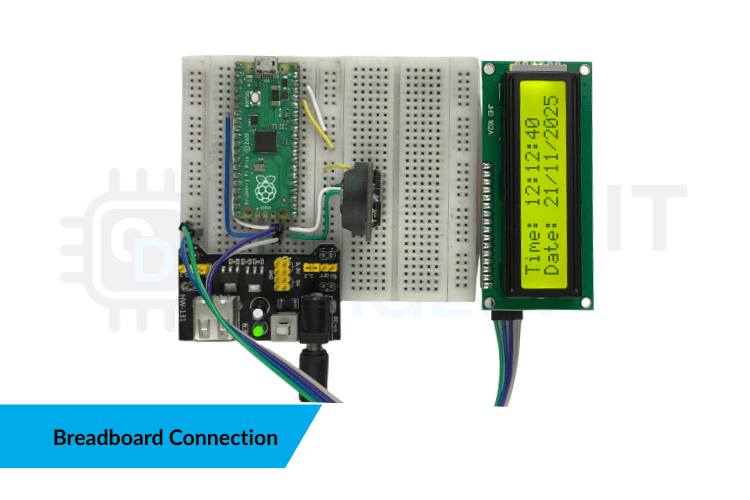
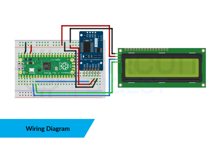
Wiring the DS3231 RTC and LCD
Use the Pico’s I²C pins to connect both the RTC and the LCD. Because I²C supports multiple devices on the same two wires (SDA and SCL), simply share these lines between the DS3231 and the LCD module. Make sure to power everything at 3.3V, as the Pico’s logic operates at that voltage.
What You’ll Need
✔ Raspberry Pi Pico — main controller
✔ DS3231 RTC Module — accurate timekeeping
✔ 16×2 I²C LCD — for displaying info
✔ Breadboard & Jumper Wires — prototyping
✔ USB Cable — to upload code
✔ Arduino IDE + Libraries (RTClib & LiquidCrystal_I2C) — to program the Pico
Arduino Code Highlights
In your sketch:
- Start I²C communication and initialise the LCD screen.
- Check that the DS3231 RTC is detected; if not, the program stops and alerts the user.
- Read the current time, date, and built-in temperature sensor from the RTC — then update the LCD every second.
By formatting the time and date into readable strings, the LCD presents a clean, dynamic display that updates in real time.
Practical Time Setup Methods
There are two useful techniques to set the RTC’s initial time:
1. Auto-set via Compile-Time Sync – embeds your computer’s current time during upload.
2. Manual Set – specify exact year, month, date and time for testing or scheduled events.
Advance Your Projects
Once you’ve mastered this interface setup, you can easily expand your system to support alarms, data logging, automation triggers, and more — all anchored to reliable timekeeping.
👉 For a wide range of beginner-friendly to advanced embedded builds, check out this curated list of Raspberry Pi Pico project tutorials and guides to spark your next innovation.