Turn a simple Arduino Uno (along with some Python code), into a crude oscilloscope to view waveforms and voltage levels.
Oscilloscopes are very useful, but usually come with a large price tag. Luckily, there are some alternatives to a dedicated oscilloscope, so in this project, we will turn a simple Arduino Uno (along with some Python code), into a crude oscilloscope that can be used to view waveforms and voltage levels!
How It Works: The Arduino
The hardware/firmware side of the oscilloscope is incredibly simple and takes advantage of a module built in to the Arduino, the ADC. The ADC, which stands for Analogue-Digital-Converter, is a module that can take an analogue voltage (between 0V and 5V), and convert it to a binary number. The Arduino has a 10-bit ADC, which means that the largest voltage, 5V, is represented as 1023 (1111111111) and the smallest voltage, 0V, as 0 (0000000000). However, since the Arduino is an 8-bit machine and unsigned chars are 8 bits in size (you will see why later), we will only use the top 8 bits from the ADC result. This means that 5V is now represented as 255 and 0V as 0V. Since there are 256 possible values, each bit represents 5/256 volts or 0.02V (approximately). Therefore, a value of 0x0F would represent 0.3V, a value of 0x80 would represent 2.56V, and a value of 0x3E would represent 1.22V.
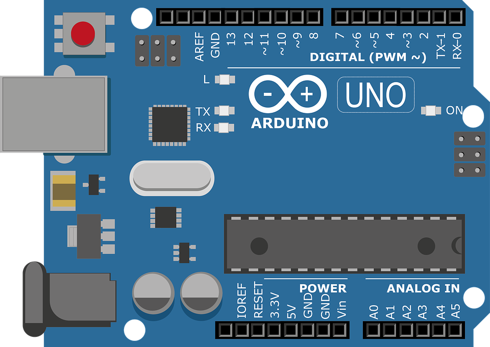
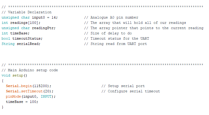
While the Arduino enables the ADC by default and thus requires no setup code, we will still configure the analogue pin as an input. The pin that we will use for taking readings will be A0, which is pin number 14. In addition to pin configuration, we will also configure the UART module to have a fast baud rate for PC communication (115200 baud), and initialize some variables.
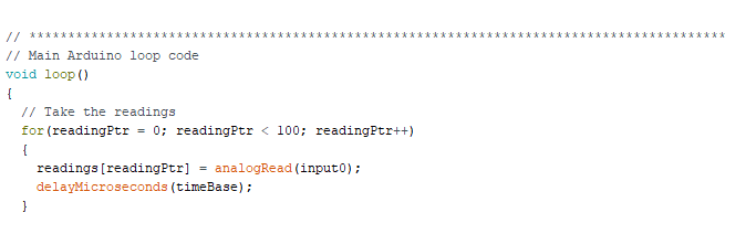
The code in our main loop starts by taking 100 readings from the ADC module. Reading analogue data from the ADC is incredibly easy and is done by using the function analogRead(pin number), which returns an integer with the 10-bit ADC result from the pin specified by pin number. In our case, input0 refers to pin 14, which is A0. Once a reading has been taken, the next piece of code to be executed is a delay. The size of the delay (in microseconds) is defined by timeBase, which is 100 by default. Despite being a 100us delay, the true spacing between readings is the size of the delay plus the ADC conversion time (100us), which gives a 200us reading spacing. For the sake of simplicity, this will be ignored in this project.
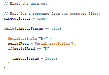
Once all 100 readings have been taken, it’s time to send this data to the PC for plotting. To ensure that the receiver can properly distinguish data transactions, the Arduino will only send data once the receiver has sent the letter "K" after the Arduino has sent the request “R?”.
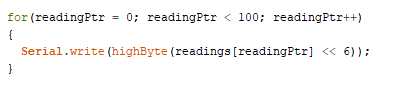
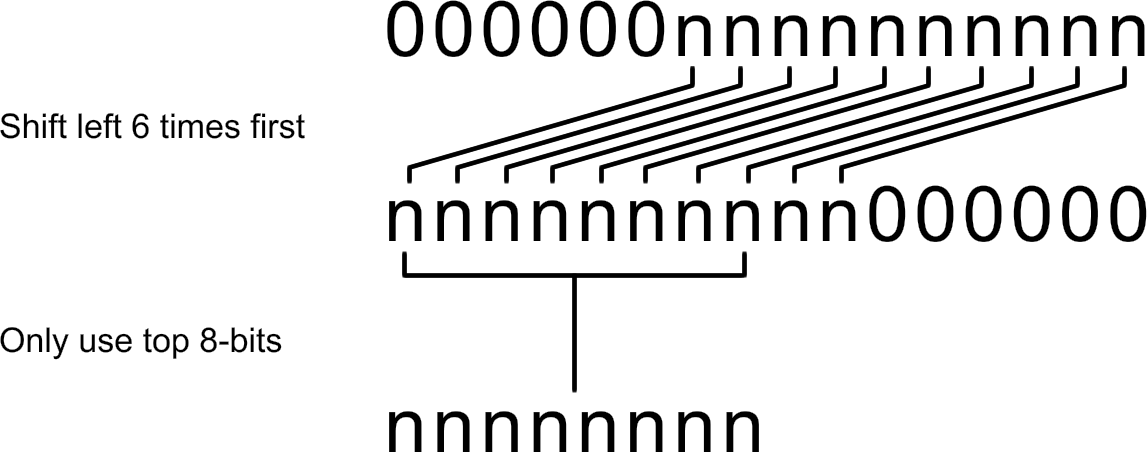
Once the Arduino and PC have successfully talked to each other, all of the data is streamed out. However, UART works on 8 bits, and trying to send integers on the UART will require complex conversions, which will make things rather difficult. Therefore, we will only send analogue readings as single bytes and we do this by using the function highByte(). Integers in the Arduino are 16 bits in size, which means we need to take our 10-bit results and shift them left until the top 8 bits contain our data. To do this, we shift our data left six times, which means we lose the lowest 2 bits of our ADC reading, but does not matter for our basic oscilloscope.
With the 8-bit results sent, the last task is to wait for a response from the computer to inform the Arduino that the results have been read correctly. The Arduino simply stays in a loop awaiting the character “K” on the serial port. Once read, the whole loop repeats itself!
How It Works: The Python Code
The Python code, along with some additional libraries, is what turns a simple Arduino data logger into a rudimentary oscilloscope. However, Python on its own cannot perform certain tasks such as graphical routines and serial port communication, so we need to obtain several libraries first. Luckily, installing these libraries is a breeze if you have PIP installed. If you do not, follow this tutorial here first to get pip. Once pip is installed, open command prompt and enter the following commands in order (one at a time):
pip install pyserial
pip install PyGame
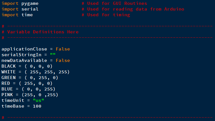
Once both of those packages have been successfully installed, we can get straight into our graphics application! While the serial package is simple to understand, the pygame package is a tad more complex, so only the basics will be covered here. The first task in our Python program is to import the needed libraries, which are pygame (for generating the graphical interface), serial (for Arduino communications), and time (for time delays). The next chunk of code is for variable declaration and initialization, which includes boolean values, strings, and colors for pygame. The colors used in pygame are of the RGB type where three bytes (0–255) represent the amount of either Red, Green, and/or Blue.
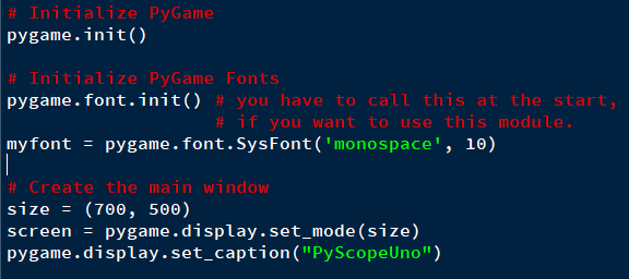
With variable definitions done, the next task is to initialize pygame, which is done by calling pygame.init(). Since we plan to print text to our window application we will also need to initialize the font engine which is done by calling pygame.font.init(). On top of initializing the font engine, we will also create a font object that we will use as our rendering font (which will be monospace). The last bit of pygame initializing code will be to create a window (size 700 by 500) and setting the title of the window to be “PyScopeUno”.
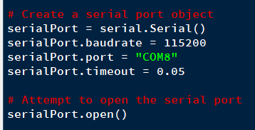
The next task involves configuring the serial port to use a baud rate that matches that of the Arduino (in this case, 115200). The correct port also has to be chosen (“COM8” in my case) and a timeout specified so that the program does not hang during serial port loops. With the serial port configured, the last step is to open the port!
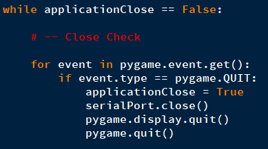
With all of the initialization code complete, the main program loop executes, which is in the form of a while loop that waits until the boolean variable applicationClose equals true. This value is set true when the close button is clicked on the window, and once clicked, the serial port is properly closed and pygame shut down.
The first task in displaying our recorded data is to obtain the serial data from the Arduino. To do this, we wait until there is data sitting in the serial port. If this data is equal to “R?”, we send the Arduino the character “K”, which results in the Arduino streaming 100 bytes to the PC. The program waits until all 100 bytes have been received, and once done, transfers these bytes to a data buffer. The next lines of code involve some basic operations that can be useful, including the calculation of the average value and finding the min/max values.
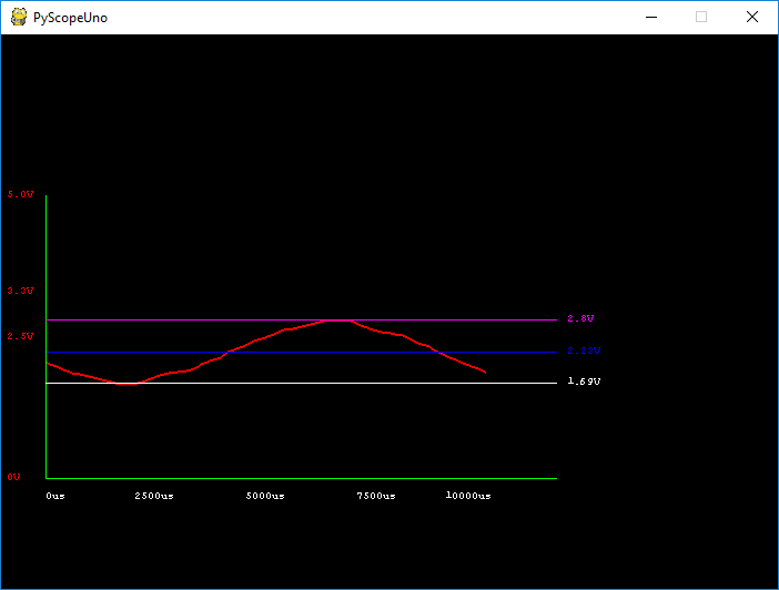
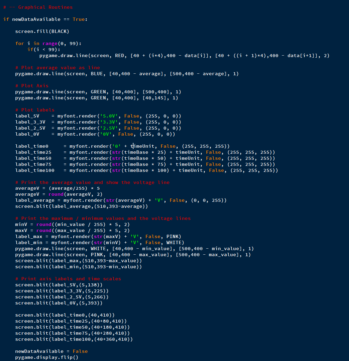
The last chunk of code involves plotting the data, drawing text, and plotting lines, but this will not be discussed in depth due to the self-explanatory nature of the code. Data in our scope program is not plotted as individual points, but as interpolated lines between two data points because fast changing signals would appear as a scatter graph, which would be hard to visualize. To do this, a line is plotted where the first point is the first voltage level and the end point is the next data value. Since we take 100 readings but our graph is 400 pixels wide, we multiply the x co-ordinates by 4 to stretch the graph out. This makes it easier to see individual readings.
The complete graphical routine is shown below.
Putting It Together
Getting this project up and running should be easy and doable in less than 15 minutes. The step that may cause the most headache is getting the Python libraries installed and working, as command line installation methods have a habit of throwing errors, not being able to find a needed file, or lacking privileges. Once the Arduino has its code loaded, it will automatically begin. Assuming the Python program works (ensure the COM port is correct), then the project should work right away.