Learn about shift registers including how they work how to use to convert parallel connections to serial connections.
Shift registers come in different versions and they can be used in a wide variety of applications. This article will introduce you to shift registers and illustrate how they work. Furthermore, it will explain how they can be used to convert several parallel data lines into a single serial connection.
What is a Shift Register?
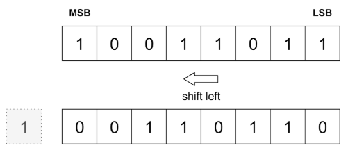
A shift register is a synchronous device that stores a single data word and can perform a logical shift operation on the bits. A logical shift moves each bit of the word either to the left or the right. Empty spaces are usually filled with zeros:
The image above illustrates a logical shift to the left. A right shift works in an analogous manner.
Shift registers consist of several single-bit latches which are connected in a serial daisy-chain arrangement so that one latch‘s output is connected to the next input:
Some shifters allow you to choose which direction the bits will be moved.
Types of Shift Registers
Generally, there are four different types of shift registers available that differ in the way the data is fed into and pushed out of the device:
- Serial input, serial output
- Serial input, parallel output
- Parallel input, serial output
- Parallel input, parallel output
Both, the serial and parallel types, usually operate synchronously and therefore you’ll need a clock signal for processing the data.
A register that supports serial and parallel inputs, as well as serial and parallel output, is referred to as a universal shift register.
Basic Operation
Let’s assume we have the following theoretical 4-bit shift register that has both, a serial in- and output, as well as parallel outputs:
As you can see, each bit gets loaded into the shift register’s D-latches from the serial input on the right.
The first clock cycle loads it into latch A. The output of the latch then has the value that got loaded into the register. The next clock cycle sets the second latch value and loads a new bit into the first latch, thereby shifting the bits from the right to the left. This happens simultaneously with all registers. The last latch output is the serial output of the shift register.
Serial shifters can, therefore, be used as buffers. The shifter from above can also be used to convert a serial signal to four parallel data lines.
Parallel to Serial Conversion
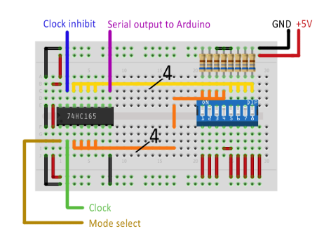
This technique can be used to reduce the number of inputs needed to read values from a parallel bus. You can, for example, utilize it to convert the signals from a computer keyboard to a single serial signal that can be understood by a USB controller. In this example, I use a DIP-switch to simulate an eight-bit data bus and I read the eight values with a single GPIO pin on an Arduino Uno:
Please note that the orange and yellow bus lines may not be connected to form a single line in reality. I decided to represent them this way to keep the image easier to understand:
The Arduino controls the shift register, generates the clock signal, and reads the eight bits. It then outputs the values:
Conclusion
A shift register is a synchronous device that consists of several D-latches and it realizes the logical shift function in digital circuits. These ICs can be used in a wide variety of applications. They are, however, often used to convert a serial data line to a parallel bus and vice-versa. When using them, you have to keep in mind that there are different types available that serve different purposes.