Learn how to interface SIM800L GSM module with Arduino
Have you ever worked with the SIM800L module for your projects? It's a handy tool for tasks like making calls and sending SMS, but sometimes it can be tricky to get it working smoothly. In this guide, we'll walk you through how to connect the SIM800L module to an Arduino Uno (Arduino GSM) and troubleshoot any issues you might encounter.
Before delving into troubleshooting, let's cover some fundamental aspects of the SIM800L module.
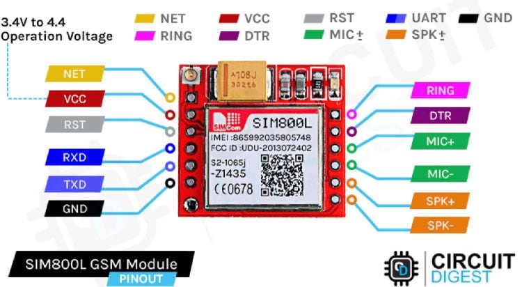
SIM800L Module
The SIM800L module is a GSM/GPRS module that offers a wide range of functionalities. It resembles a small chip with an antenna connector and various pins. The below image shows the sim800lpinout, this will later be useful when we are connecting the sim800l gsm module with Arduino.
Powering the SIM800L GSM Module
Ensuring a stable power supply is essential. The SIM800L module requires an input voltage of 3.7V to 4.2V, which may differ from typical electronics. Using a buck converter with a 2A or higher capacity or a 3.7V Li-ion battery can meet this requirement. The current capacity of the buck converter mentioned must be greater than or equal to 2A because the GSM module is a power-hungry device specifically when sending messages or calls . Adding a capacitor between VCC and GND can further stabilize the power supply, but the module works without that too.
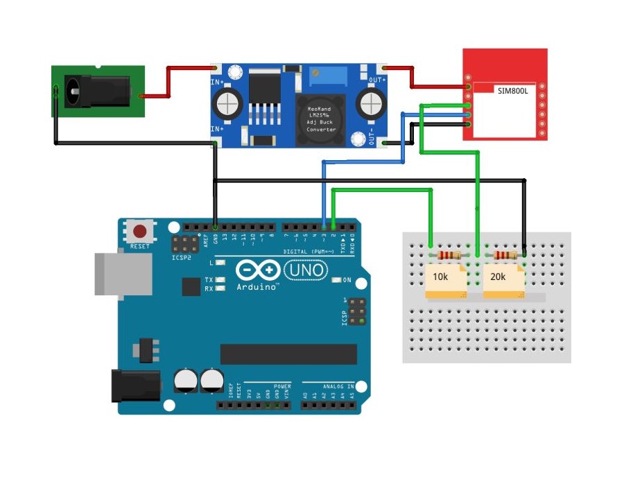
Connecting SIM800L with Arduino UNO
When interfacing with a microcontroller like Arduino, voltage compatibility is crucial. Since the module operates at 3.3V while many microcontrollers operate at 5V internally, proper level-shifting is necessary to prevent damage. Utilizing a voltage divider is common to adjust voltage levels.
You can see in the above sim800l Arduino wiring diagram that I've used one 10k resistor and one 20k resistor in series to create a voltage divider and convert the 5V to 3.3V, but you can use different values too. I've used a voltage divider calculator to figure out the resistor values. You can try changing the values too.
SIM800L AT Command Test
Uploading an AT command test program to your Arduino allows you to communicate with the SIM800L module. The easiest way to test if your SIM800L GSM module is working or not is by using a simple AT command test, the below image shows how the SIM800L is powered and the LED blinks once every 3 seconds to indicate that it is ready with the network. Then by sending a simple AT command, we can check if the GSM module is giving an OK. Make sure you have uploaded the below code in your Arduino before sending commands to the SIM800L module. Alternatively, you can also use a USB to TTL converter in place of Arduino and test for the same.
// Create a SoftwareSerial object to communicate with the SIM800L module
SoftwareSerial mySerial(3, 2); // SIM800L Tx & Rx connected to Arduino pins #3 & #2
void setup()
{
  // Initialize serial communication with Arduino and the Arduino IDE (Serial Monitor)
  Serial.begin(9600);
  // Initialize serial communication with Arduino and the SIM800L module
  mySerial.begin(9600);
  Serial.println("Initializing...");
  delay(1000);
  mySerial.println("AT"); // Handshake test, should return "OK" on success
  updateSerial();
  mySerial.println("AT+CSQ"); // Signal quality test, value range is 0-31, 31 is the best
  updateSerial();
  mySerial.println("AT+CCID"); // Read SIM information to confirm whether the SIM is inserted
  updateSerial();
  mySerial.println("AT+CREG?"); // Check if it's registered on the network
  updateSerial();
}
void loop()
{
  updateSerial();
}
void updateSerial()
{
  delay(500);
  while (Serial.available())
  {
    mySerial.write(Serial.read()); // Forward data from Serial to Software Serial Port
  }
  while (mySerial.available())
  {
    Serial.write(mySerial.read()); // Forward data from Software Serial to Serial Port
  }
}
Ensure that the module responds with "OK" to confirm its responsiveness. If this is working for you and you are feeling adventurous you can also test the Call and SMS capability in the same set-up by just typing in a different command.
Sending SMS in SIM800L using Arduino
The SIM800L module supports making calls and messages.
Below is the Arduino code for sending a message on SIM800L. You just need to change the phone number (+XXXXXXXXXXXX)and text which you need to send and upload the code.
Here’s the complete sim800l SMS Arduino code for the same.
#include <SoftwareSerial.h>
// Create a SoftwareSerial object to communicate with the SIM800L module
SoftwareSerial mySerial(3, 2); // SIM800L Tx & Rx connected to Arduino pins #3 & #2
void setup()
{
  // Initialize serial communication with Arduino and the Arduino IDE (Serial Monitor)
  Serial.begin(9600);
  // Initialize serial communication with Arduino and the SIM800L module
  mySerial.begin(9600);
  Serial.println("Initializing...");
  delay(1000);
  mySerial.println("AT"); // Handshake test, should return "OK" on success
  updateSerial();
  mySerial.println("AT+CMGF=1"); // Configuring TEXT mode
  updateSerial();
  mySerial.println("AT+CMGS=\"+ZZxxxxxxxxxx\""); // Change ZZ with the country code and xxxxxxxxxxx with the phone number to send an SMS to
  updateSerial();
  mySerial.print("Circuitdigest | circuitdigest.com"); // SMS text content
  updateSerial();
  mySerial.write(26); // Send the CTRL+Z character to terminate the SMS
}
void loop()
{
}
void updateSerial()
{
  delay(500);
  while (Serial.available())
  {
    mySerial.write(Serial.read()); // Forward data from Serial to Software Serial Port
  }
  while (mySerial.available())
  {
    Serial.write(mySerial.read()); // Forward data from Software Serial to Serial Port
  }
}