In this tutorial, we are going to learn about FOR loop, WHILE loop, and the Map function of BlocklyDuino.
To further explore the FOR loop, WHILE loop, and Map function we will also utilize a potentiometer, a pulse width modulation signal, and a servo motor. We will do three exercises based on these topics.
A Quick Recap of Part 1
The previous article, How to Program an Arduino Using BlocklyDuino, began with instruction on installation and initial setup of the program. If you haven’t used BlocklyDuino before, I highly recommend you begin with that tutorial.
From there, we learned how to use digital input/outputs and IF-ELSE condition statements in BlocklyDuino. We performed an LED blinking test using the DigitalWrite and Delay blocks. Then, through a switch, we controlled (turned ON/OFF) an LED using the DigitalRead and IF-ELSE conditional blocks.
Fading and Brightening an LED using the FOR loop
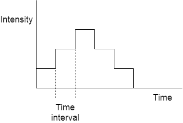
In this exercise, we are going to change the intensity of an LED’s brightness, first low to high, then high to low, and so on. To achieve this, we have to change the intensity of LED at every step, i.e., after fixed intervals, like the ladder/step graph shown below.
So now the question is how are we going to change the intensity of LED? By using the AnalogWrite block!
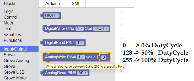
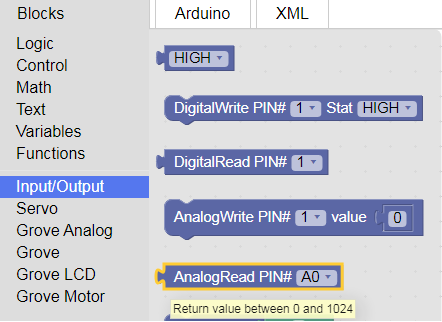
The AnalogWrite block is located in the Input/Output tab of BlocklyDuino. It outputs different voltage levels per the specified PWM value entered by the user.
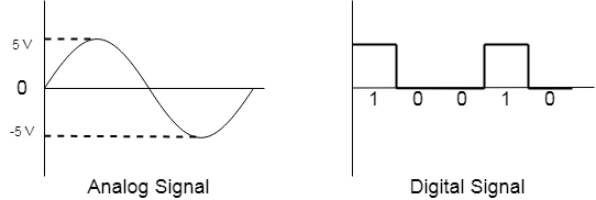
This block uses the concept of pulse width modulation (PWM). A PWM signal is a combination of analog and digital signals. For those who don’t know, the digital signal is a wave which can achieve only two voltage levels either high (1) or low (0), whereas the analog signal is one which can have an infinite number of voltage levels in the given range (e.g., 0V to 5V).
A visual of the difference between analog and digital signals
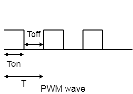
PWM is a combination of analog and digital, meaning that its nature of wave is similar to a digital signal but it can have an infinite number of voltage levels similar to an analog signal. The voltage generated by the PWM wave is called the average voltage. Let’s look at how the PWM wave exhibits this property. Start by taking a look at the graph below.
T is the total time taken to complete a single wave and Ton and Toff are the ON time and OFF time of the pulse, respectively. The ratio of Ton to total time is called the duty cycle.
Duty Cycle:
By changing the duty cycle and keeping the same frequency, we can generate different voltage levels.
There is also a formula to calculate the average voltage generated by the PWM wave. Remember that there is a difference between the average voltage and Vcc of Arduino.
Average Voltage = (DutyCycle/100)*Vcc
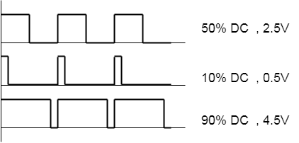
The image below shows PWM waves with different duty cycles and average voltage.
PWM waves with different duty cycles and average voltage.
With an understanding of the AnalogWrite block and PWM, next up is the FOR loop block.
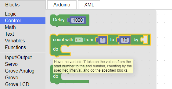
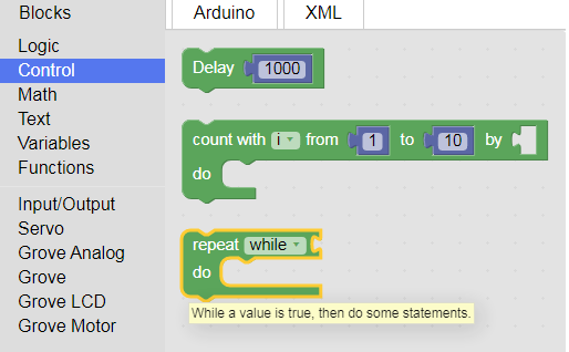
The FOR loop block asks for two arguments viz start, and endpoints of count variable. It starts incrementing/decrementing counter variables from the set start point and goes up to the endpoint. So, code presented inside this loop wil; execute again and again until this variable is in the range of the start and endpoint. This block can be found in the Control tab of BlocklyDuino.
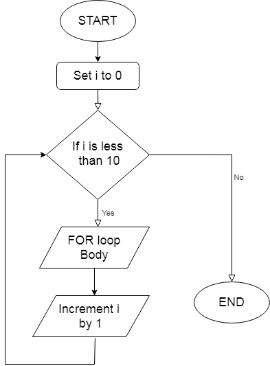
To give a better understanding, I have designed a flowchart of the FOR loop below.
Flowchart of the FOR loop
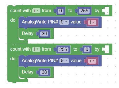
To achieve our task of LED fading and unfading, we are going to use both the AnalogWrite and FOR loop blocks.
First, we will set our start and endpoint of the FOR loop to 0 and 255 and inside the FOR loop we change the PWM value of the LED at every instant by using the i(count) variable. Once it reaches 255, it starts another FOR loop back at zero. Simultaneously, at every instant, we change the PWM of the LED.
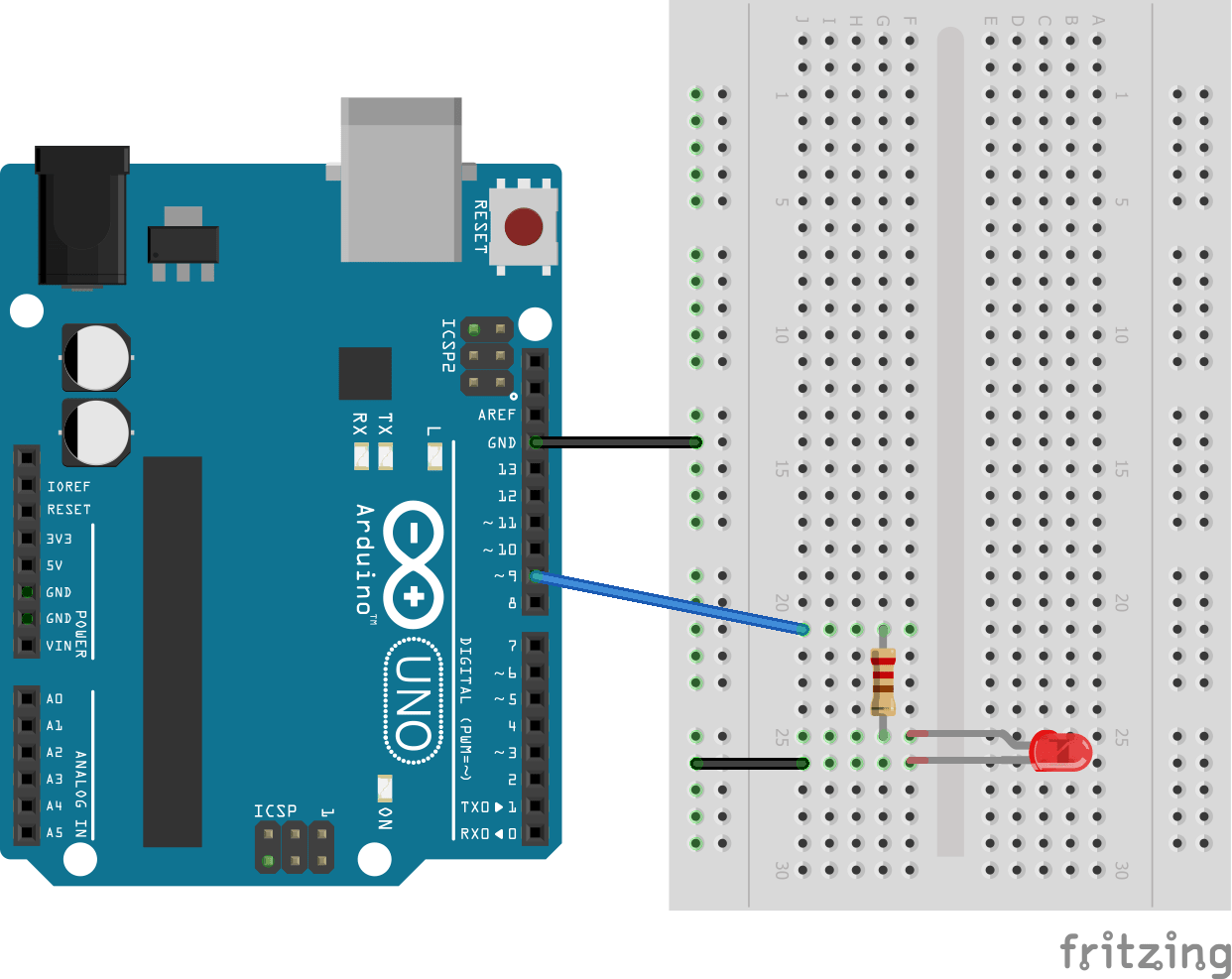
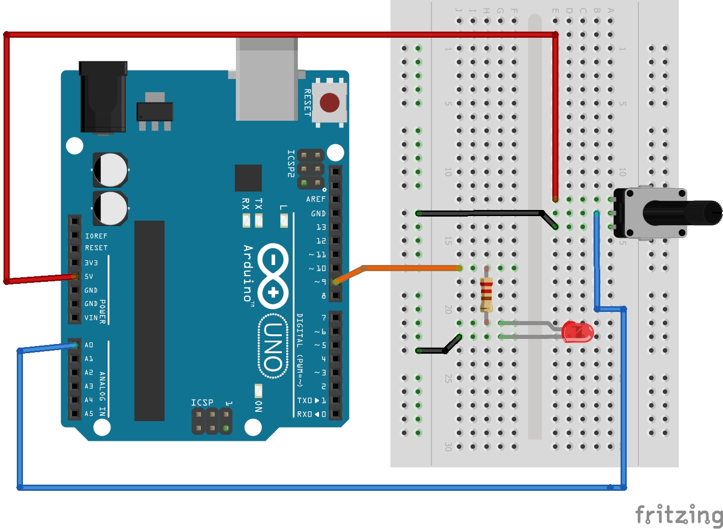
Hardware connection and code are given below for your reference.
Copy the auto-generated Arduino code into Arduino IDE.
Compile the code and download it onto your Arduino board. Once the programming is done, observe the fading and brightening of the LED. Try to change the delay in the FOR loops and write in the comment section below what difference you observed!
Reading the Potentiometer and turning ON/OFF LED Using the WHILE Loop
Let us first discuss the potentiometer. A potentiometer is simply a variable resistor that can be used to source variable voltage and current. The general diagram of the potentiometer is shown below.
A potentiometer has three terminals: the middle terminal is a slider and both end terminals are for power (Vcc & Gnd). The middle slider breaks the overall resistance of the potentiometer and creates two different resistors as shown in Figure B above. A 10kohm potentiometer means that the overall resistance between the two end terminals is 10kohm, but, with the help of the slider, we can generate variable resistance across any end terminal and slider.
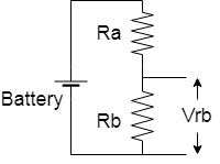
Here we will use a potentiometer as a voltage divider. The image below how a potentiometer can be used as a voltage divider.
A common voltage divider (A) and a potentiometer as a voltage divider (B).
The voltage obtained at the second resistor end is calculated by the following formula:
We are going to read this voltage at the Arduino’s analog input pin and control LED. First, let's make the hardware connections.
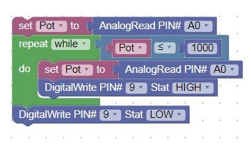
The Arduino's ADC reads this voltage from the analog pin and returns a value in the range of 0-1023. We use the AnalogRead function block to read a value from the analog pin and the WHILE loop to monitor this reading. The WHILE block can be found from the Control tab and the AnalogRead block is located in the Input/Output tab.
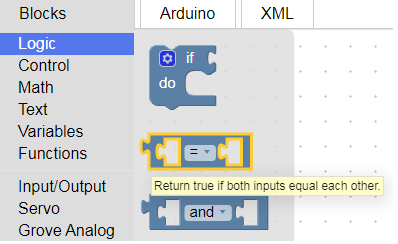
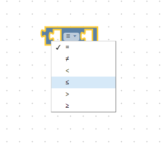
We have to specify the correct analog pin number in the AnalogRead function. In the WHILE loop, we have to pass a condition block, which can be found in the Logic tab.
In the conditional block, the program has to pass two arguments for comparison and select the mode of comparison. The code written inside the WHILE loop will be executed again and again until the set condition is satisfied.
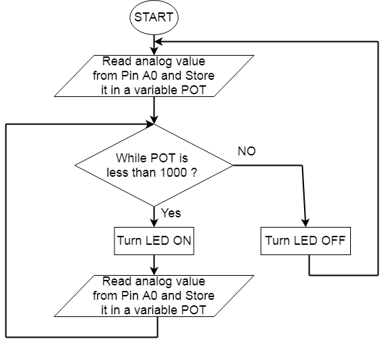
The flowchart below shows a visual understanding of what we want to achieve.
Copy the auto-generated Arduino code into Arduino IDE
Compile the code and download it onto your Arduino board. Once programming is done, observe LED turning ON/OFF by moving the potentiometer.
Reading the Potentiometer Value and Controlling a Servo Motor
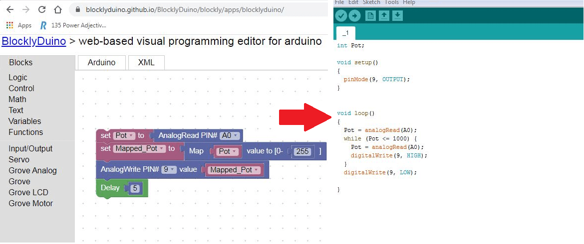
In the previous section, we discussed potentiometers and how to read their value using the AnalogRead block. In this exercise, we are going to use this potentiometer value (0-1023) to set the position of a servo motor.
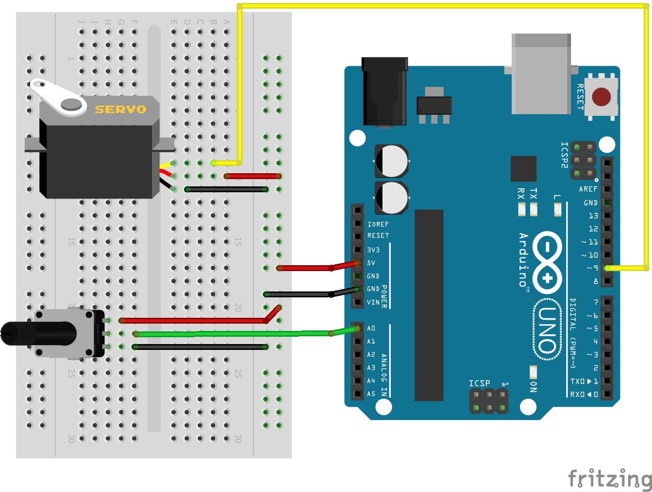
A servo motor has three pins: Vcc, Gnd, and PWM input. Connect all three pins to Arduino as shown in the diagram below.
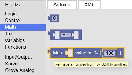
Servo motors can be controlled using PWM pulses from an Arduino. The AnalogWrite function’s block range is 0-255, so we have to convert the potentiometer’s reading to the output PWM value range. For this, we use the Map function, which is an inbuilt function of Arduino. The Map block can be found in the Math tab.
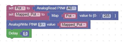
We need to specify the expected output range (0-255). Here is the screenshot of the code:
Copy the auto-generated Arduino code into Arduino IDE
Compile the code and download it onto your Arduino board. Once programming is done, observe the servo motor’s position change.
A Recap of What We Learned
In this tutorial, we discussed pulse width modulation signals and how to output a PWM signal from Arduino using the AnalogWrite block. By using the FOR loop, we changed the PWM value at every instant and controlled the intensity of the LED.
We also learned about the potentiometer and how to read its analog value using the AnalogRead block. We then monitored the potentiometer’s value using the WHILE loop and turned an LED ON and OFF based on a threshold potentiometer reading.
In the final exercise, we used both the AnalogRead and AnalogWrite blocks to read POT value and control a servo motor. We also learned about the Arduino’s built-in Map function and its uses.
I hope you enjoyed learning more about programming your Arduino using BlocklyDuino. If you have any difficulty while using Blockly, feel free to post in the comment section!