The XRC PRO is an advanced, open-source RC transmitter and receiver system designed to offer professional-level performance in a compact and customizable package. Built around the STM32F103C8T6 microcontroller and the NRF24L01 wireless transceiver module, the XRC PRO provides precise, real-time control for various RC applications like drones, cars, and boats. With a compact design, robust functionality, and user-friendly interface, the XRC PRO is an ideal tool for both hobbyists and professionals.
A Support From PCBWAY
This project was made possible with the incredible support and sponsorship from PCBWay. Their assistance allowed me to bring my ideas to life, and I am grateful for their commitment to supporting creators in the DIY and maker community. Thank you, PCBWay, for believing in this project!
PCBWay also offers a variety of services, including PCB assembly, 3D printing, and CNC machining. Their sponsorship program for projects like this one helps make electronics projects more accessible to everyone. By choosing PCBWay, you can bring your projects to life with confidence.
➡️ Check out PCBWay and get your first PCB for FREE : Click Here.
Supplies
Transmitter Components
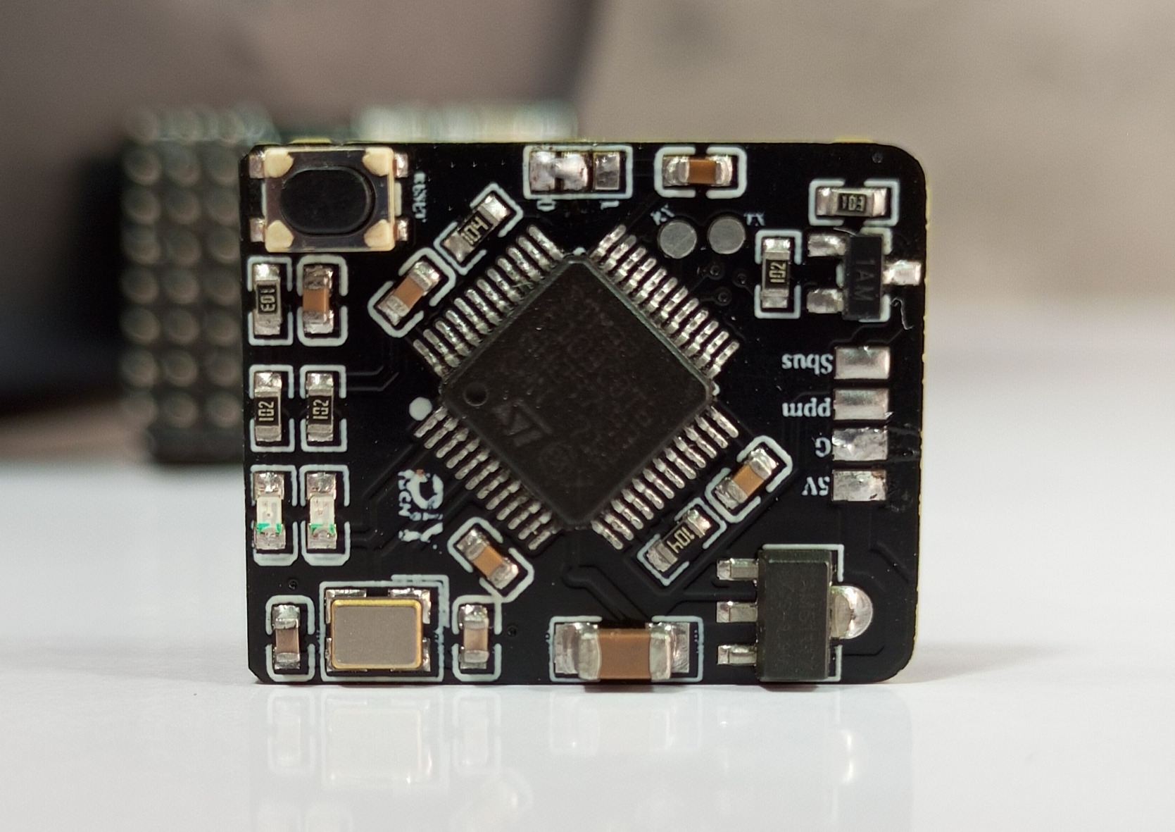
1).STM32F103C8T6: ARM microcontroller (desoldered from development board and soldered to transmitter PCB)
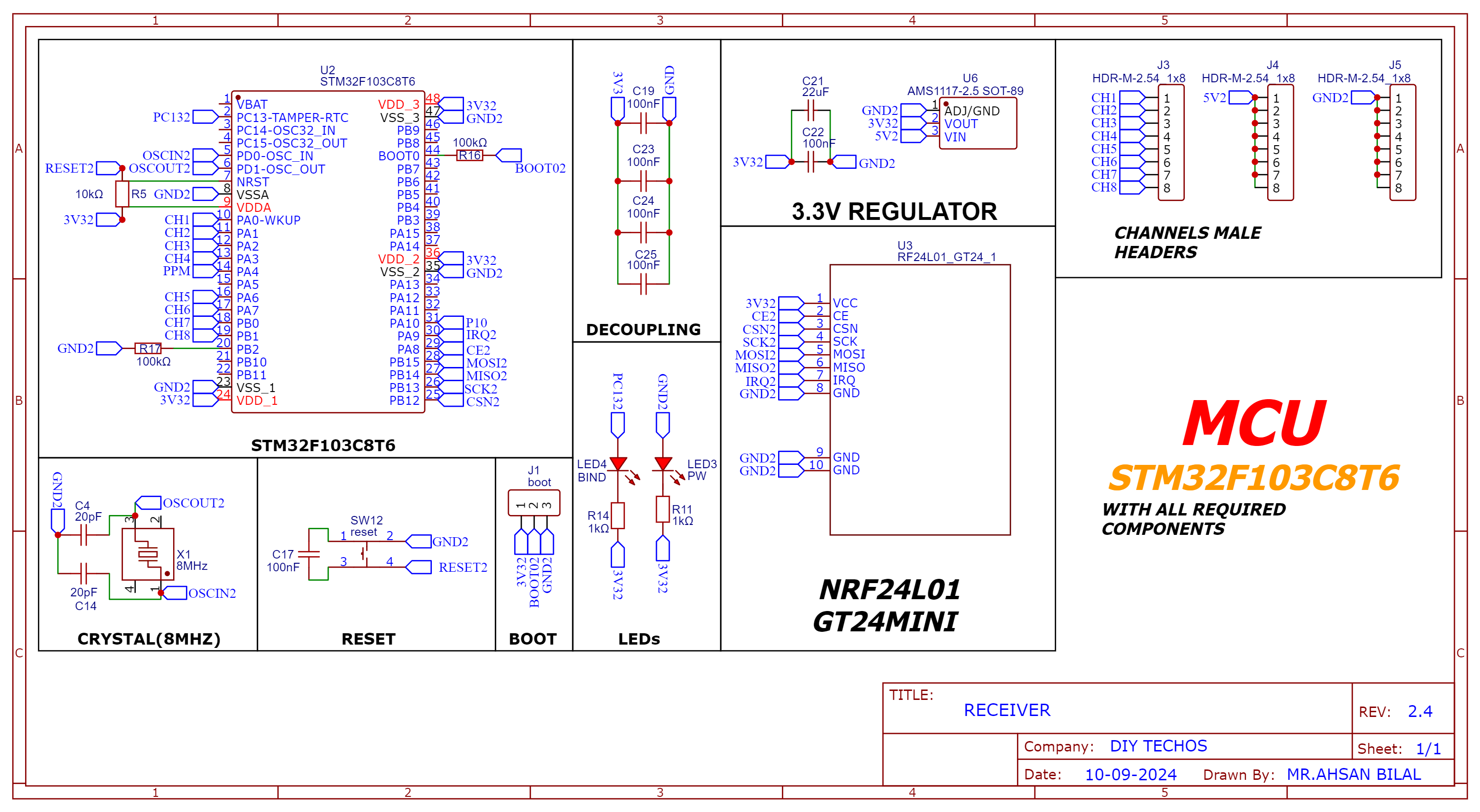
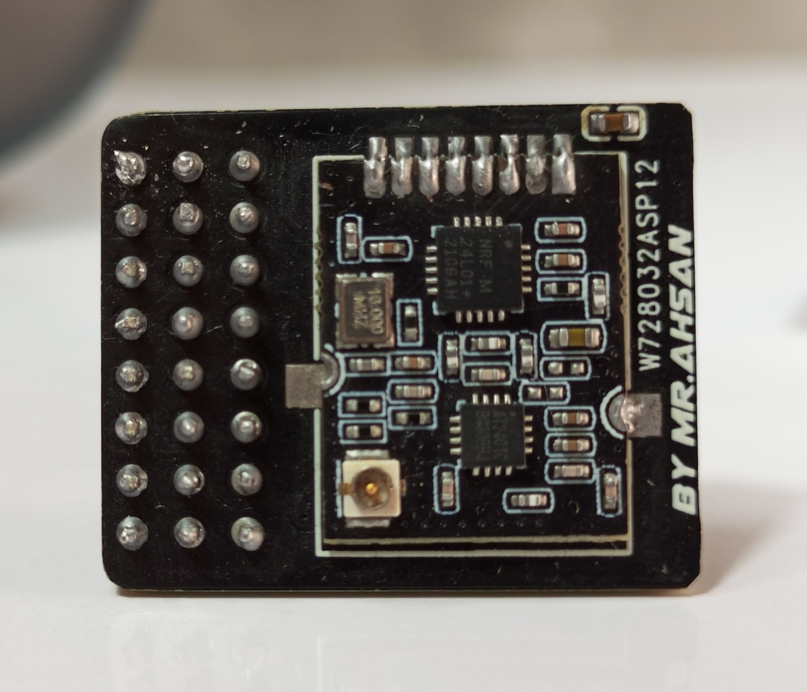
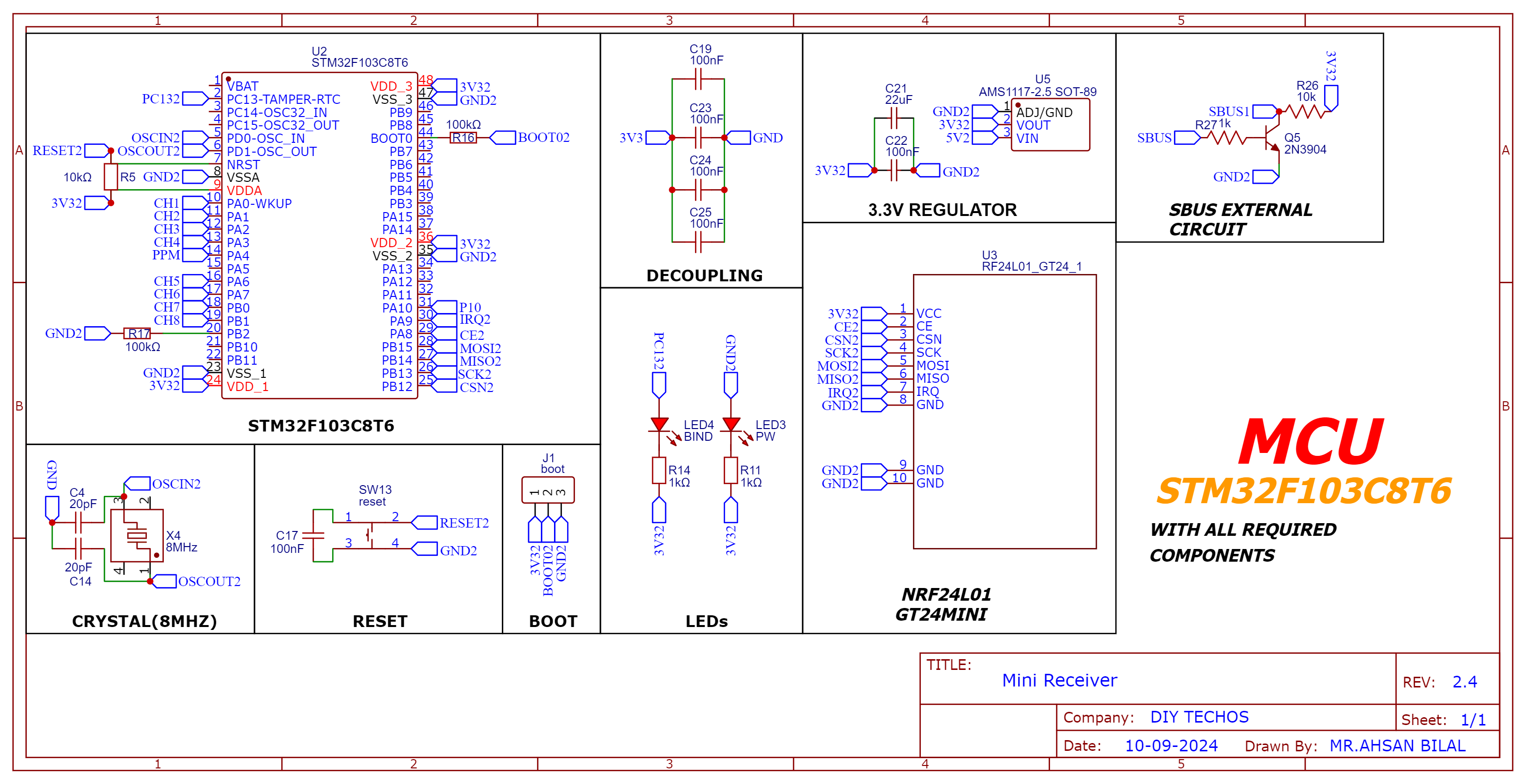
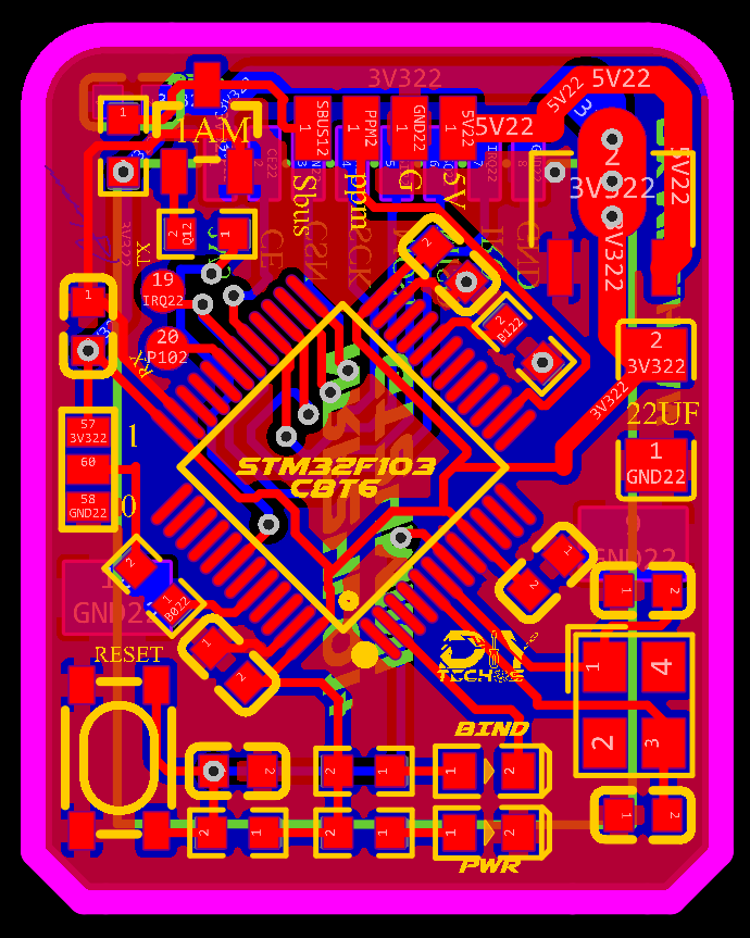
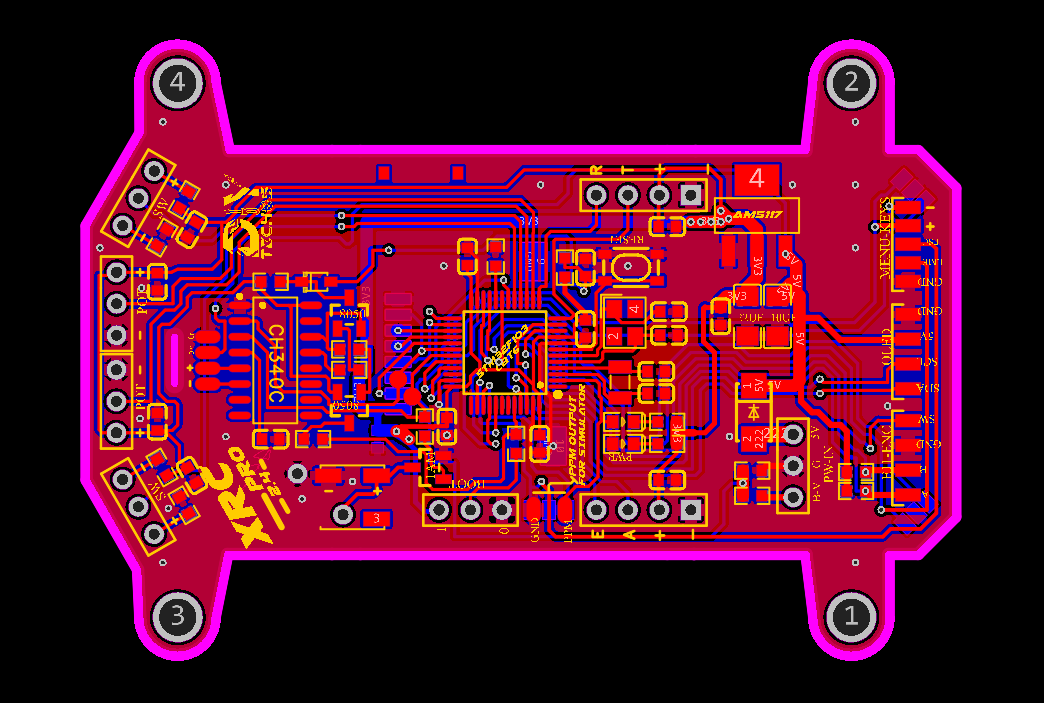
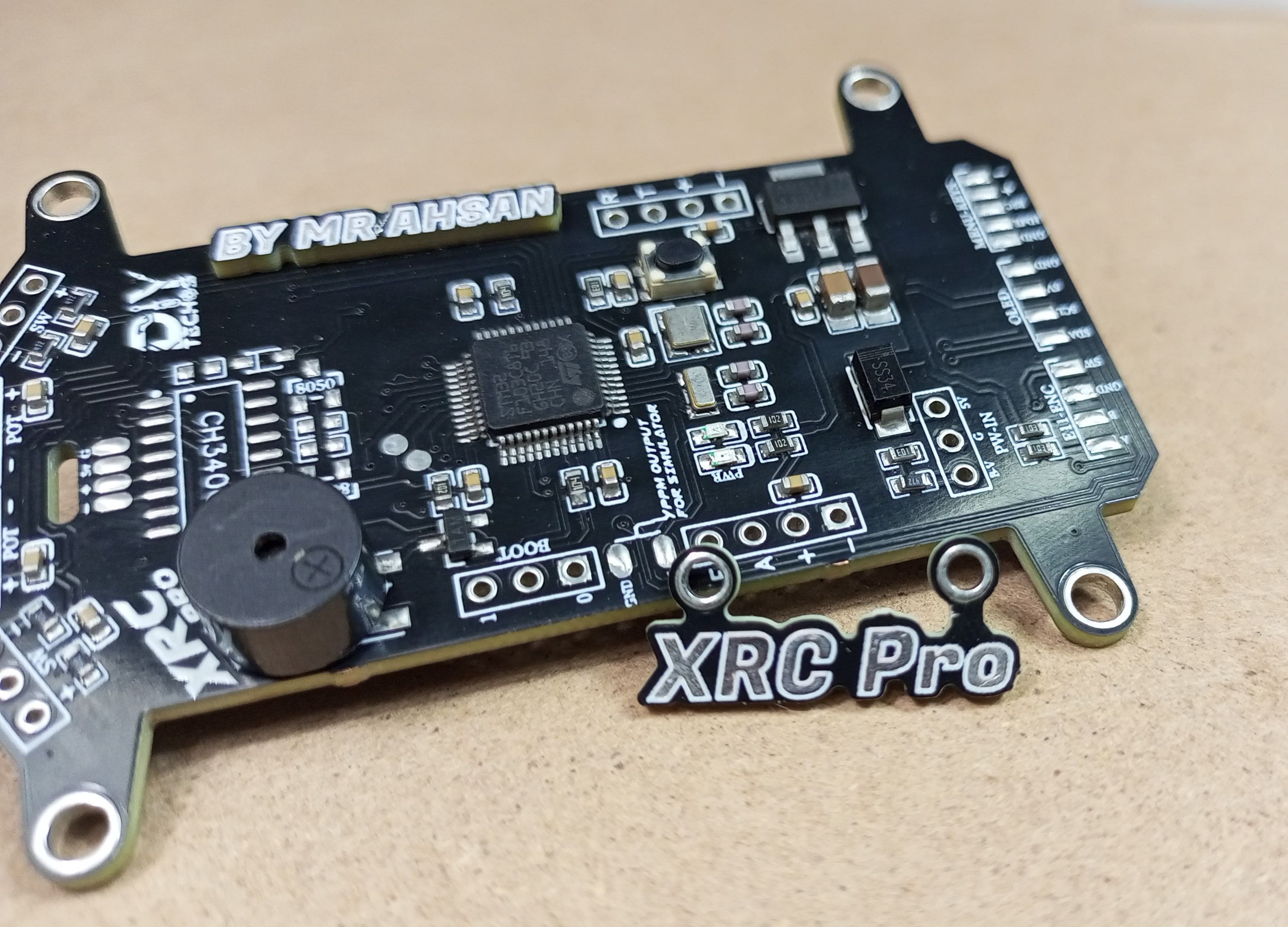
The XRC PRO has multiple PCBs and it consists of three main PCBs: the Transmitter PCB, the 8-channel PWM+PPM Receiver PCB, and the PPM+SBUS Receiver PCB. Each PCB was carefully designed for space efficiency and optimal performance.
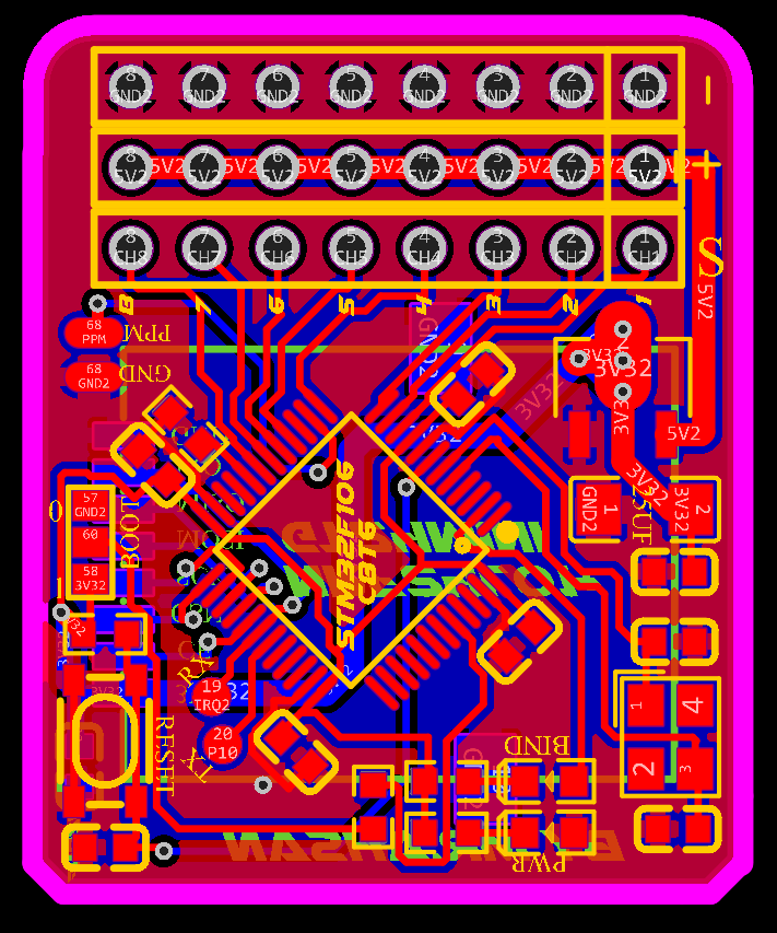
Transmitter PCBs
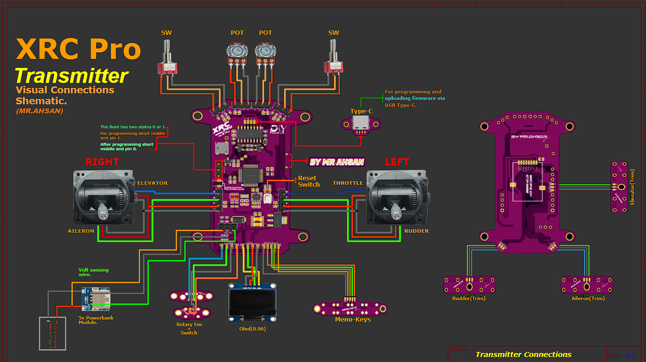
The Transmitter PCB is built around the STM32F103C8T6, NRF24L01 module, OLED display, and various input buttons (trim, menu, encoder). The schematic includes connections for power management (5v to 3.3v), data lines for the OLED, and button inputs for settings navigation etc.
Schematic and PCB Layout
2D and 3D Preview
Final Result
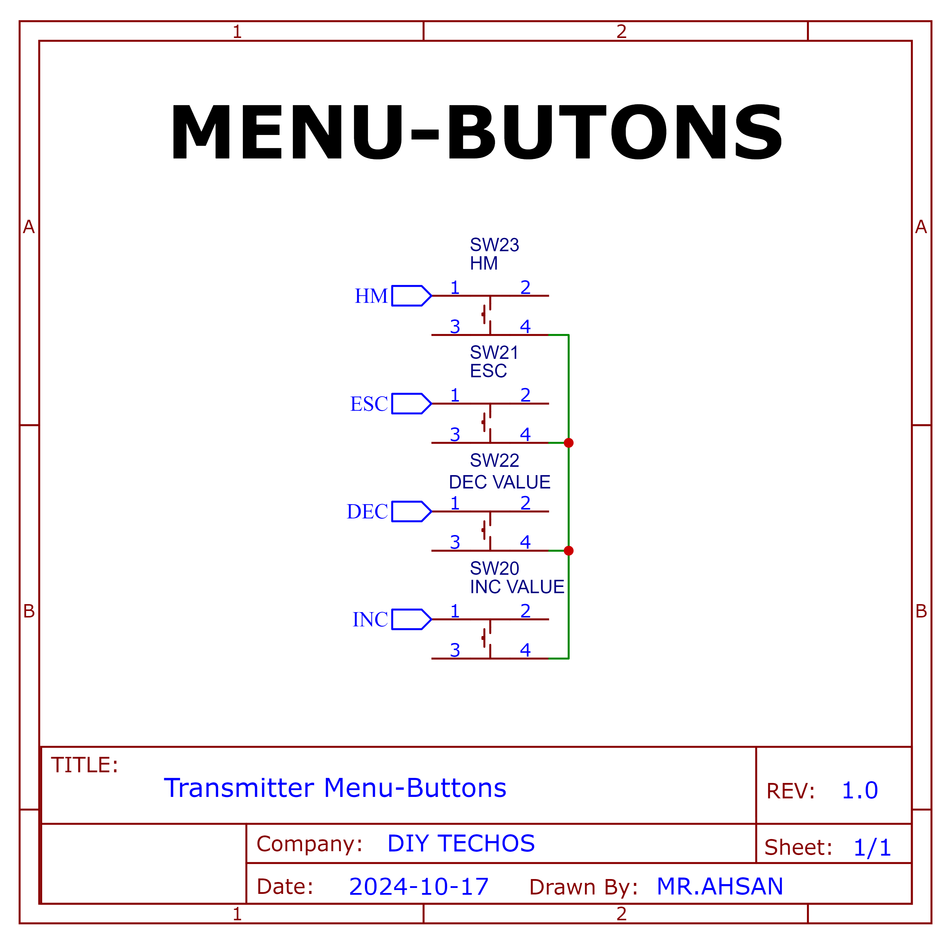
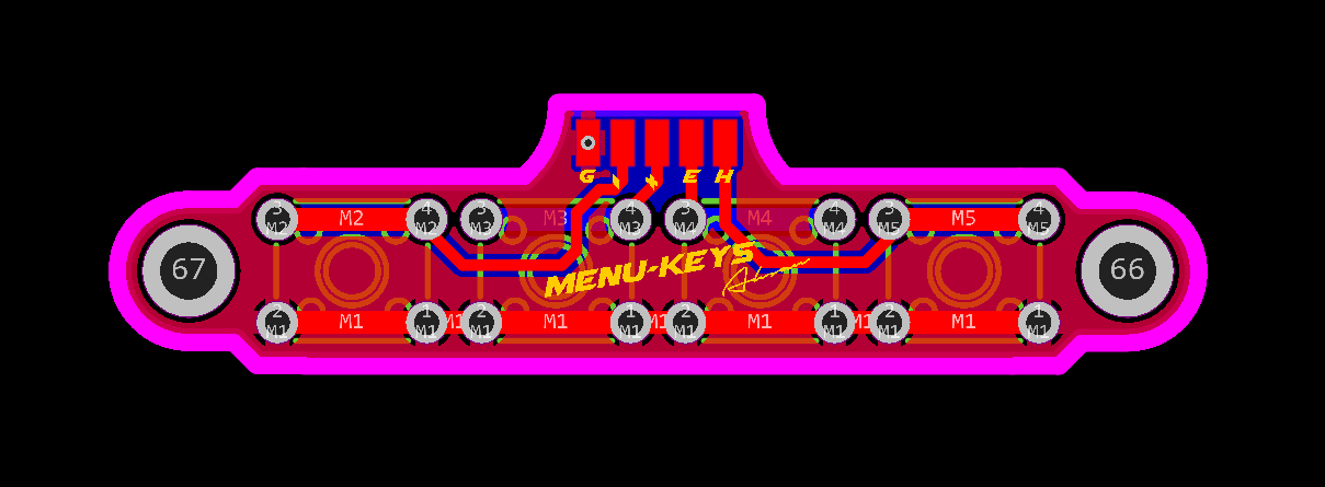
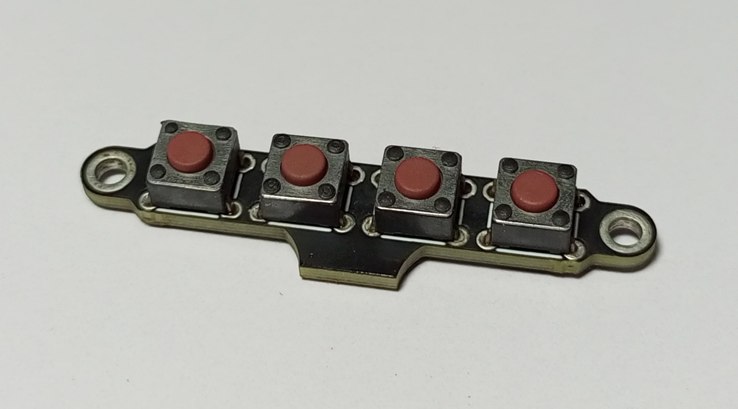
Menu-Keys
Schematic and PCB Layout
2D and 3D Preview
Final Result
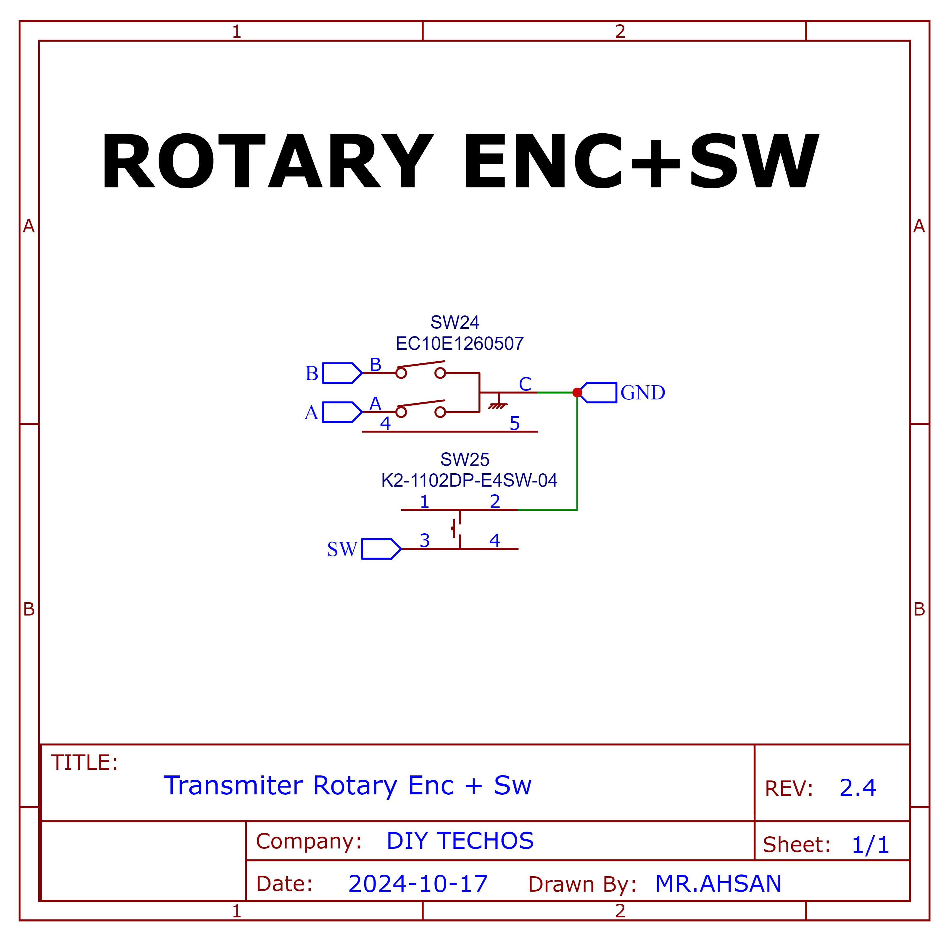
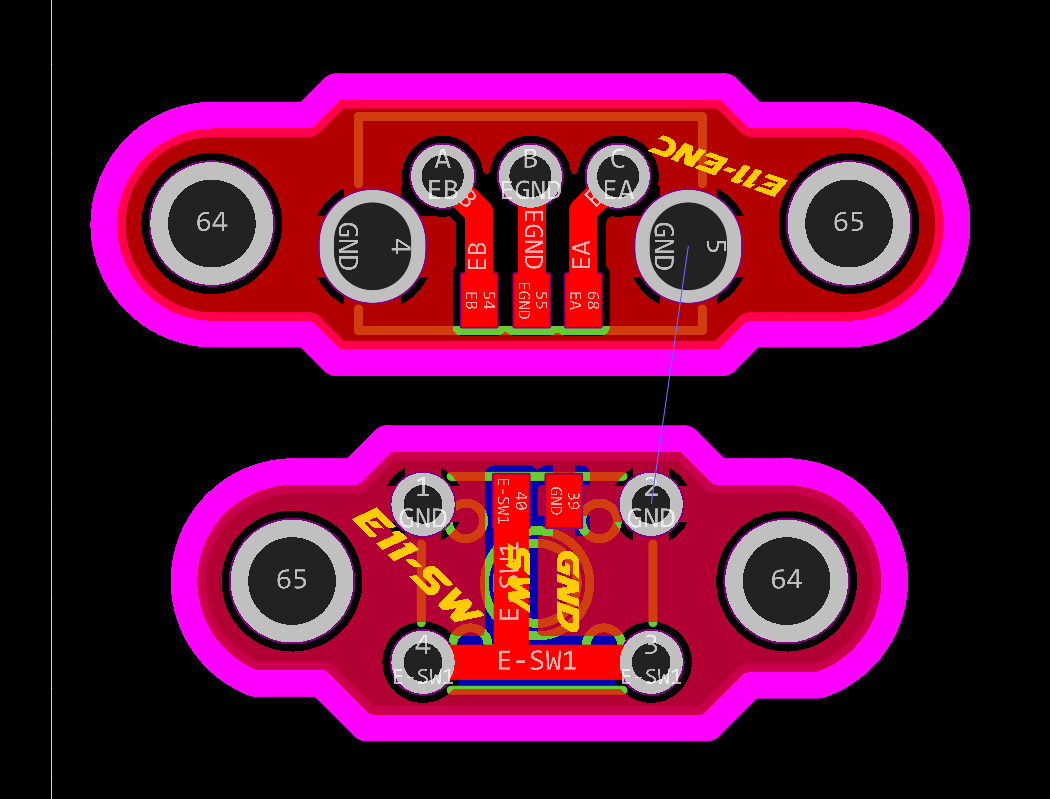
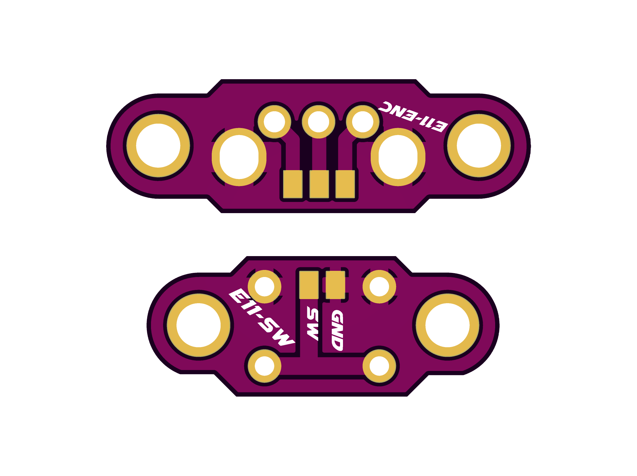
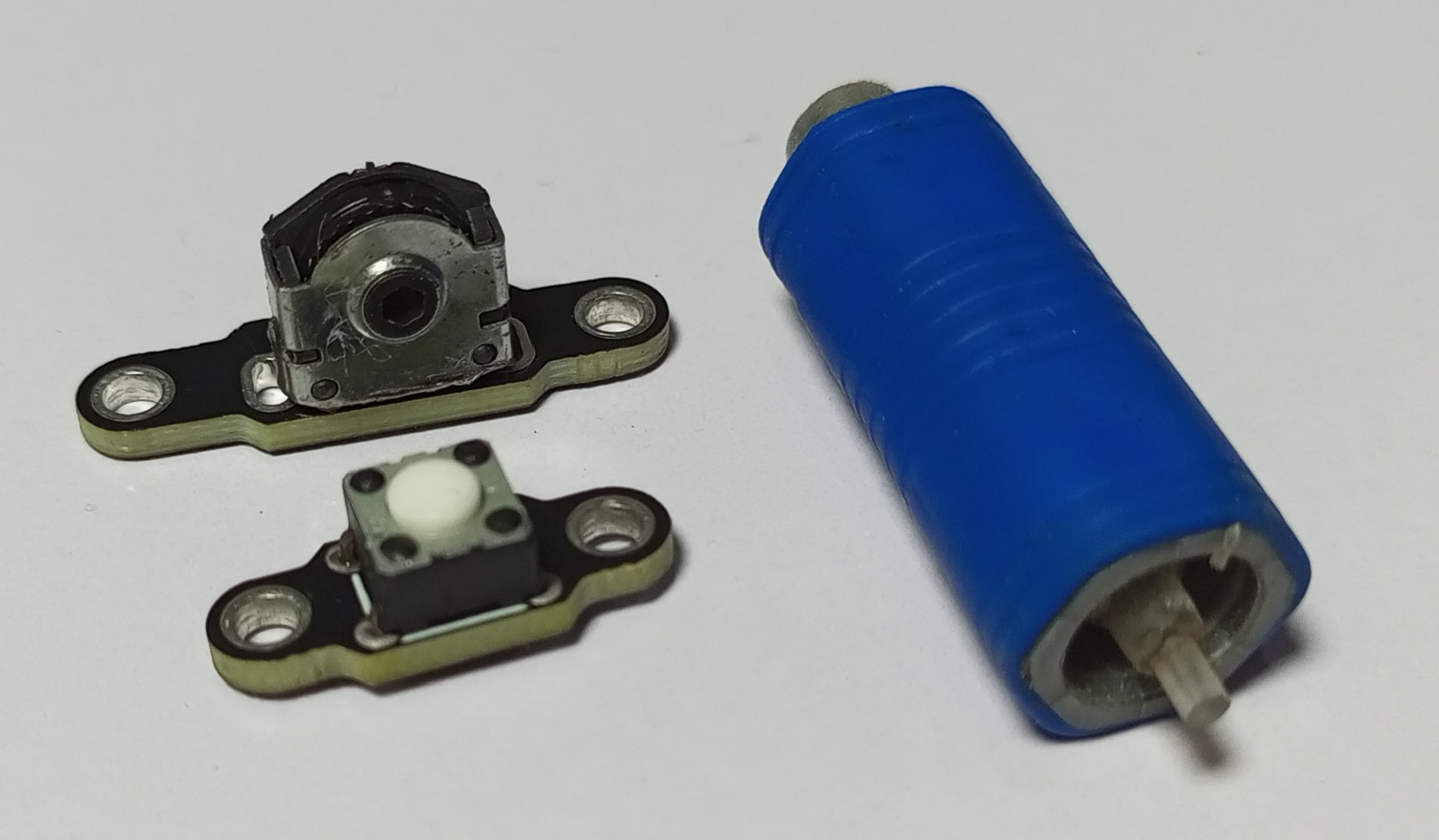
Rotary Encoder+Switch
Schematic and PCB Layout
2D and 3D Preview
Final Result
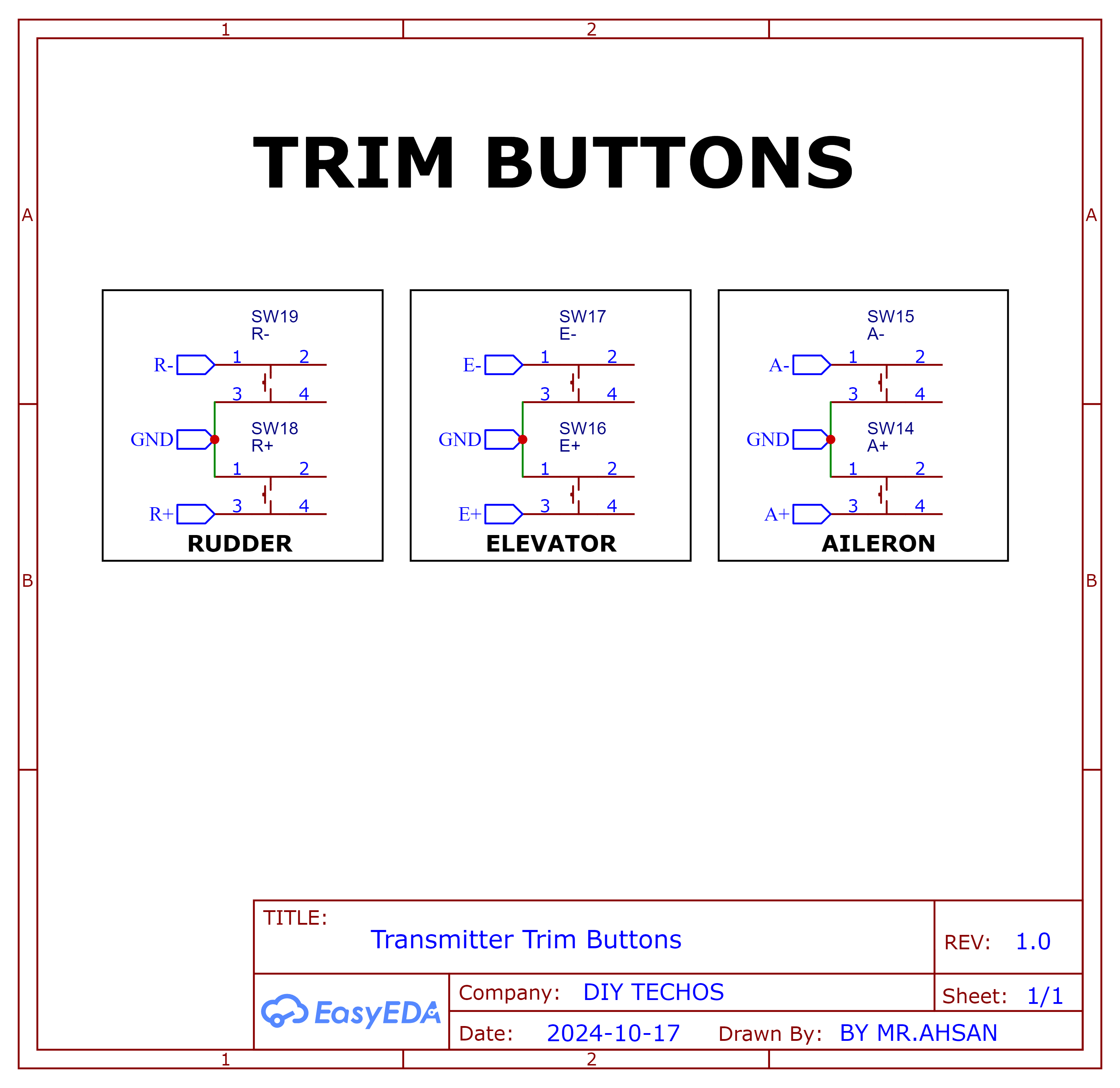
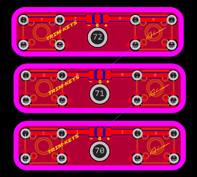
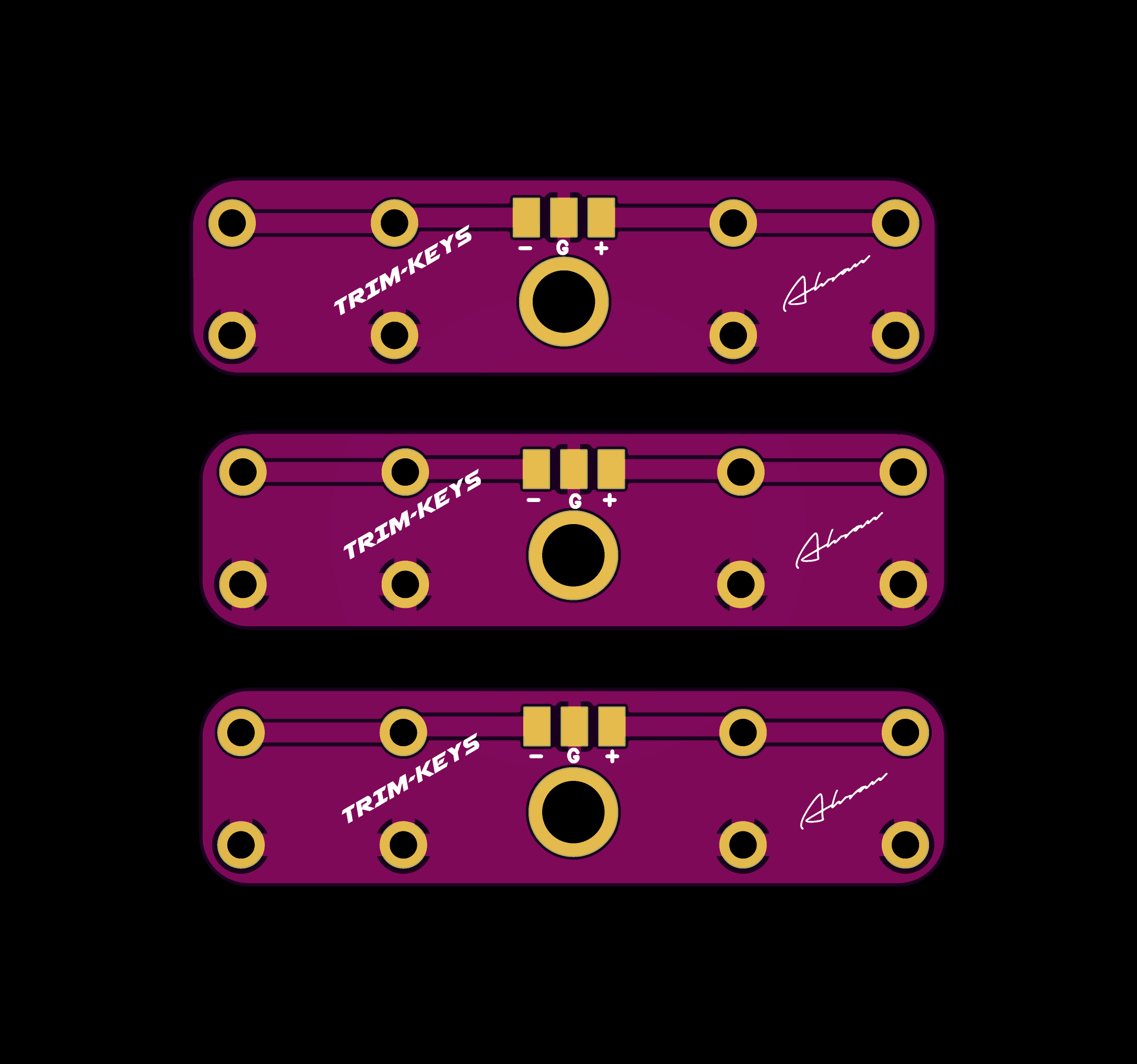
Trim Buttons
2D and 3D Preview
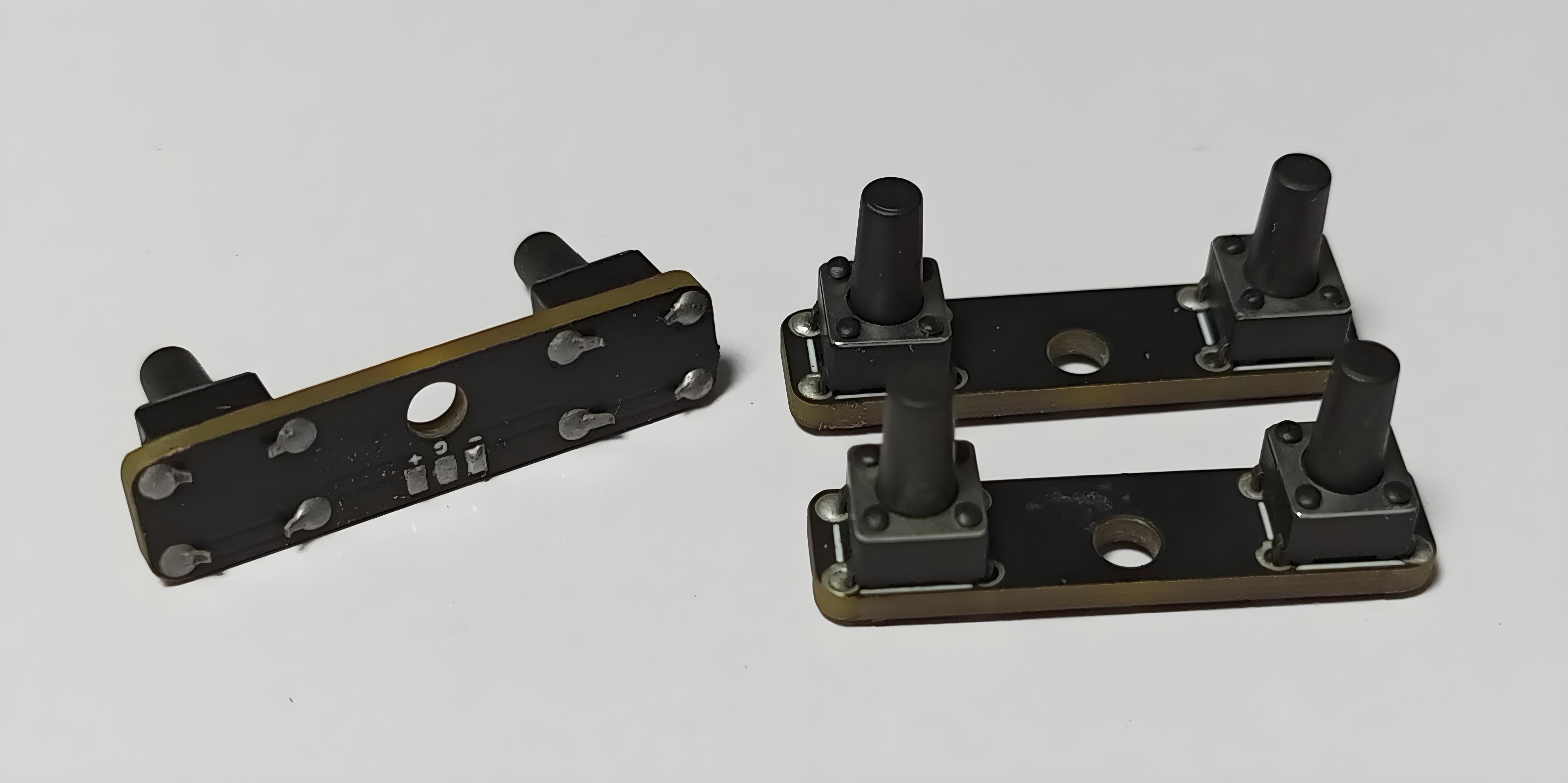
Final Result
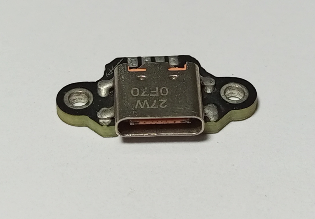
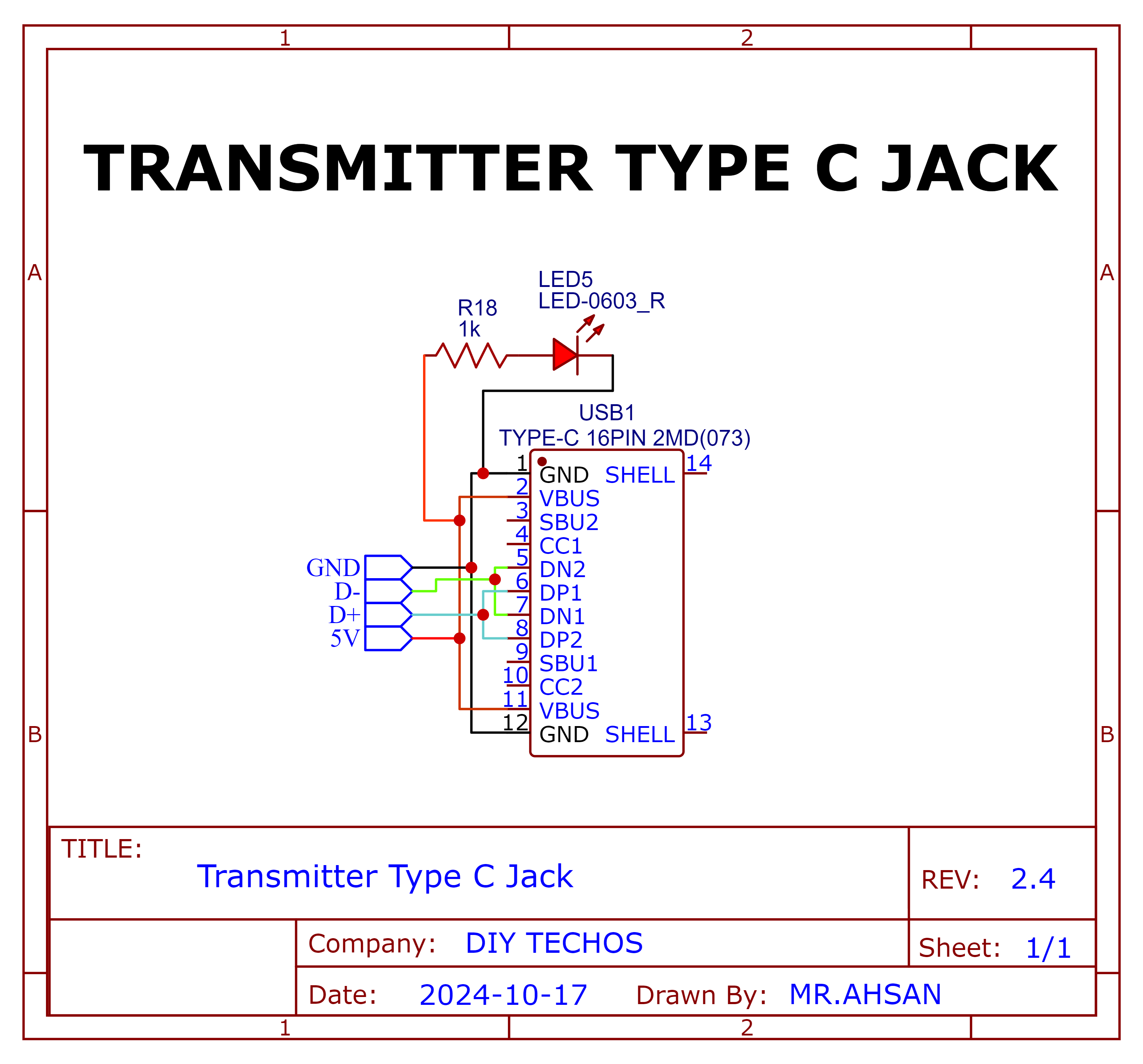
Type C Jack
Schematic and PCB Layout
2D and 3D Preview
Final Result
Receciver PCBs
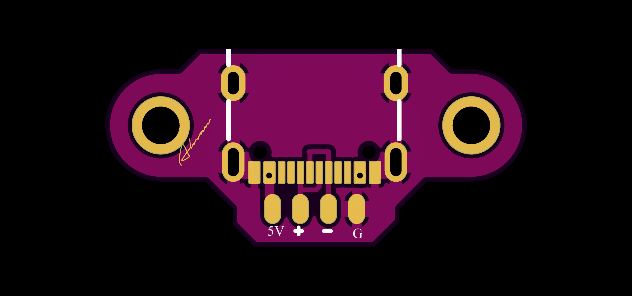
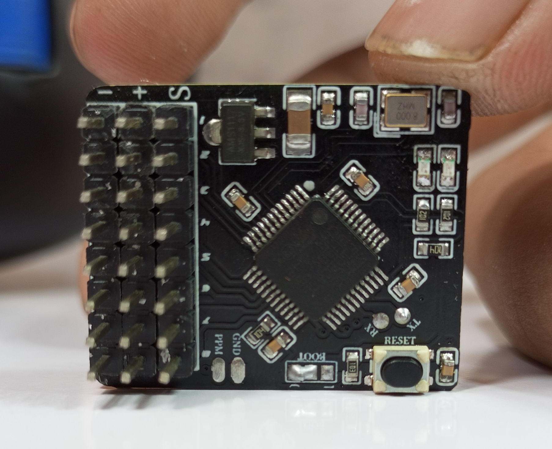
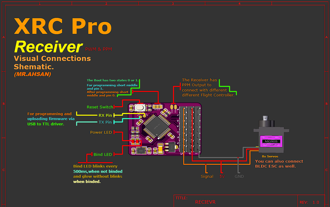
8-channel PWM+PPM Receiver PCB
The 8-channel receiver supports both PWM and PPM outputs. It is based on the NRF24L01 and STM32F103C8T6 for signal decoding and generation.
Schematic and PCB Layout
2D and 3D Preview
Final Result
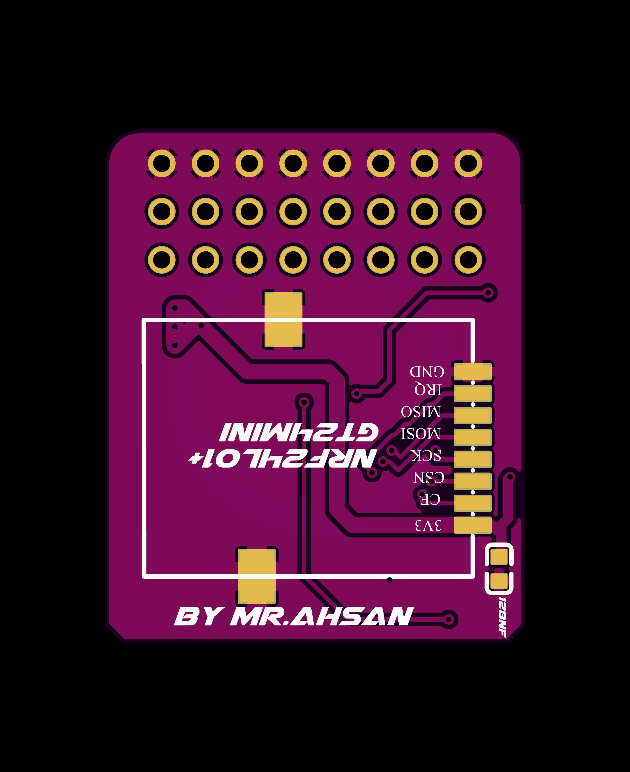
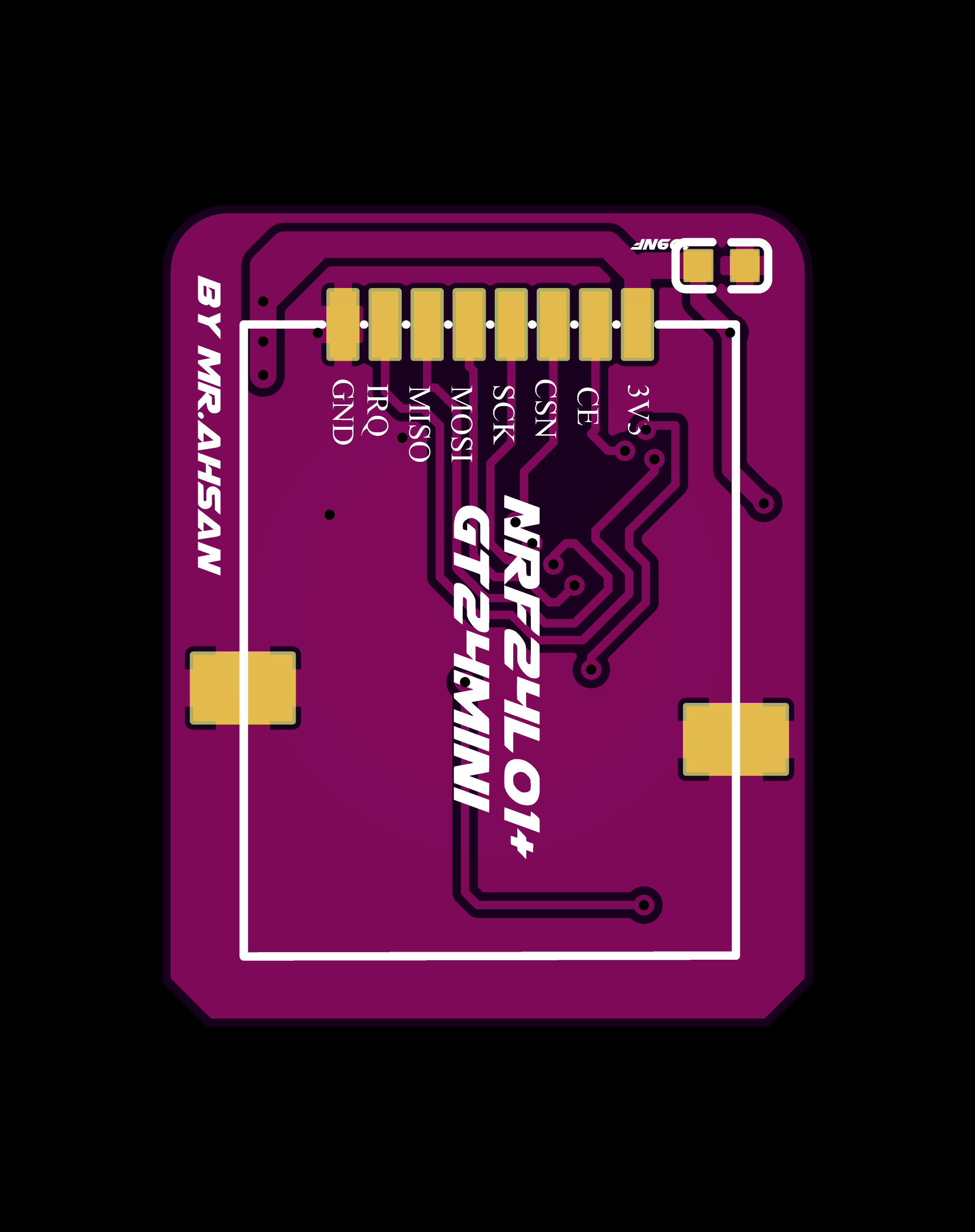
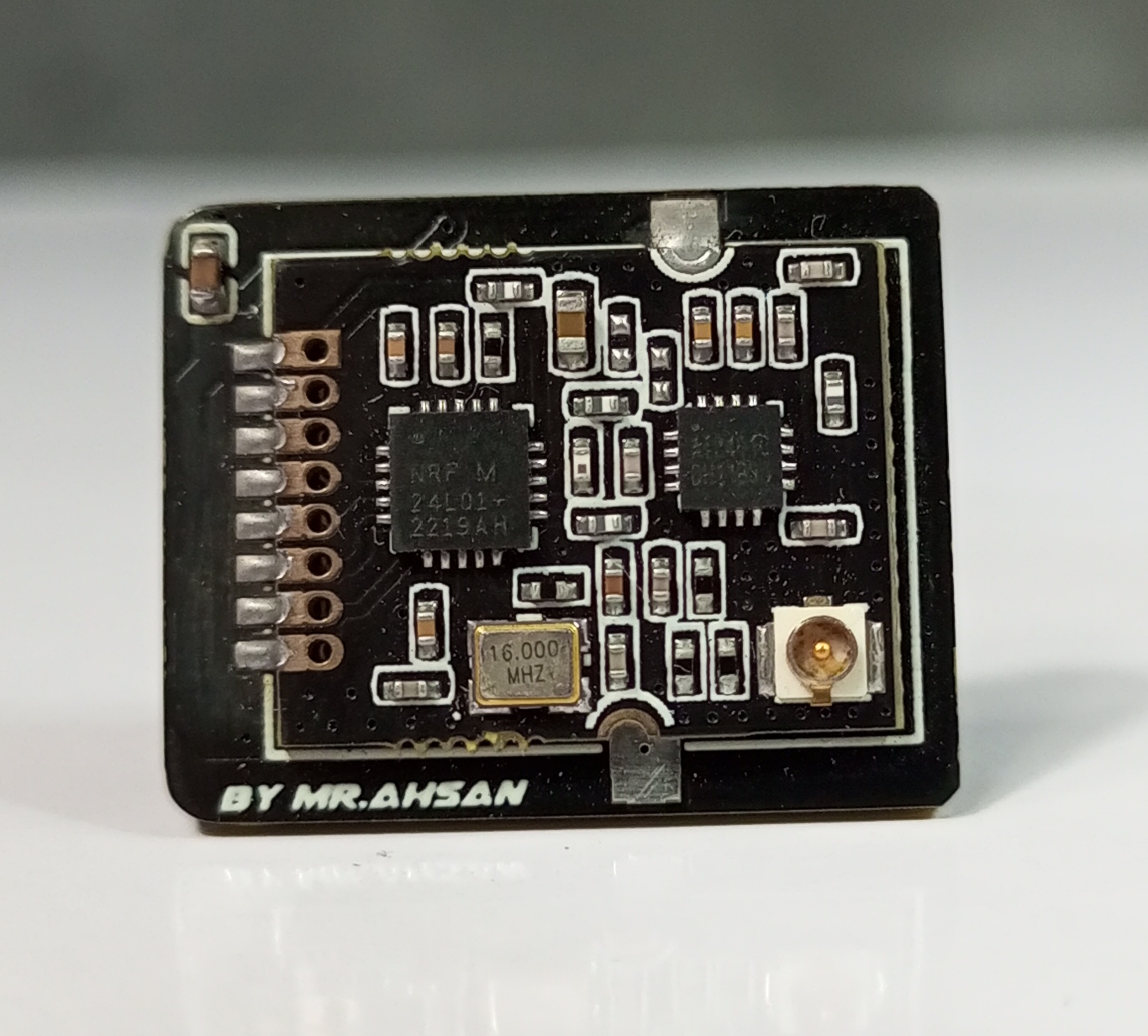
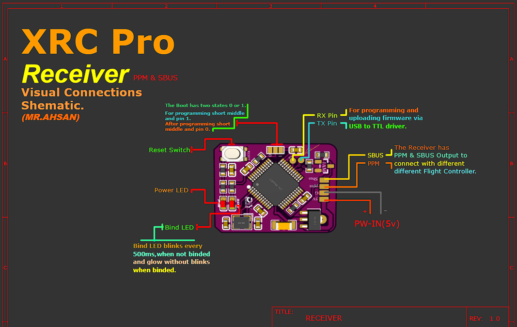
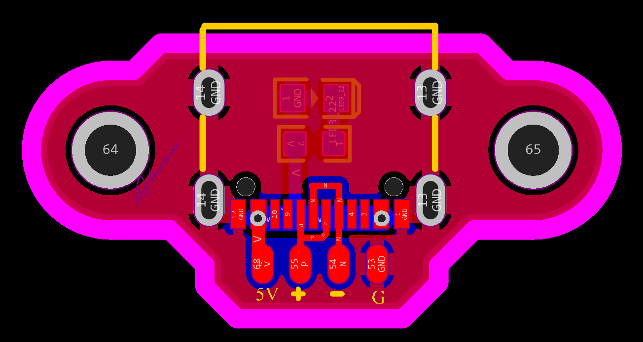
PPM+SBUS Receiver PCB
The PPM+SBUS receiver is another compact design focused on supporting more advanced control protocols. It also features the STM32F103C8T6 for signal processing and output.
I’ve designed a detailed, color-coded connection schematic for all inputs and outputs, making it easy for anyone to assemble the XRC PRO transmitter and receivers. Additionally, I’ve included high-quality these images in PDF format, which you can download below.
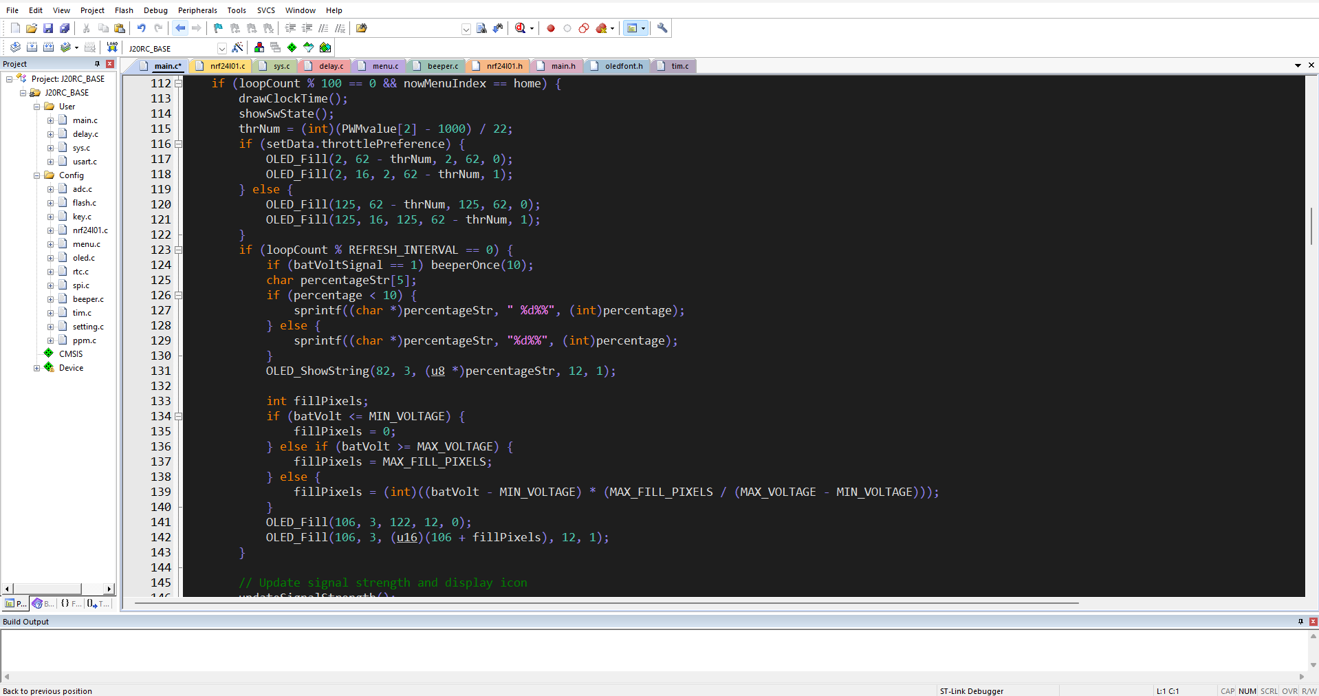
The XRC PRO's firmware is developed in Keil uVision using the CMSIS framework for STM32. It is fully open-source, with modular code to allow easy customization and extension of the system's capabilities. The main focus of the firmware is on handling communication between the transmitter and receivers, as well as managing the various control inputs.
Here the whole files in KeiluVision:
Below are the functions broken down from the main execution code, organized into smaller functional blocks. These functions are intended to be modular and handle specific tasks like initialization, signal strength calculation, display management, and event handling:
1. setup()
This function initializes all the necessary hardware peripherals and sets up the system for operation.
void setup() {
// Initialize the delay function for timekeeping
delayInit();
// Initialize USART for serial communication
usart1Init();
// Initialize timers for PWM and other timing-related functions
timer2Init();
timer3Init();
// Initialize DMA for memory transfers
dmaInit();
// Initialize ADC for analog reading (e.g., battery level)
adcInit();
// Initialize NRF24L01 for wireless communication
if (nrf24l01Init() == NRF_OK) {
nrf24l01SetModeTX(); // Set NRF to transmit mode
} else {
// Handle NRF24L01 initialization error
beepError();
}
// OLED display initialization and show start-up screen
oledInit();
oledShowLogo();
// Perform throttle self-check and configure NRF24L01 power mode
throttleSelfCheck();
// Set up low-power mode if necessary
lowPowerModeConfig();
}
2. loop()
The main loop that continuously runs during operation. It handles the display updates, signal strength checks, and key events.
void loop() {
// Handle clock alarms and time display on the OLED
handleClockAlarm();
// Update OLED display with throttle values and battery percentage
displayThrottleValues();
displayBatteryLevel();
// Update signal strength display
updateSignalStrength();
// Check for key events and menu navigation
keyEventHandle();
// Handle menu events, if any
menuEventHandle();
// Small delay to avoid constant polling
delay(50);
}
3. keyEventHandle()
Handles user input through key presses. This function updates throttle settings and processes navigation within the menu.
void keyEventHandle() {
if (isKeyPressed(KEY_LEFT)) {
// Adjust throttle channel for left-hand throttle
adjustThrottleLeft();
}
if (isKeyPressed(KEY_RIGHT)) {
// Adjust throttle channel for right-hand throttle
adjustThrottleRight();
}
// Update OLED display with new throttle or menu setting
oledRefresh();
// Save user data or preferences (e.g., throttle setting)
saveUserDataToFlash();
}
4. addSignalStrengthSample()
Adds a new sample to the signal strength buffer and maintains a moving average of signal strength.
This function measures the signal strength by sending multiple packets and calculating the percentage of successful transmissions.
int getSignalStrength(void)
{
const int totalPackets = 40; // Total number of packets to send
int successfulPackets = 0; // Counter for successful transmissions
if (setData.NRF_Mode == ON) // If the NRF mode is ON
{
NRF24L01_TX_Mode(setData.NRF_Power); // Set NRF to transmit mode
}
else
{
NRF24L01_LowPower_Mode(); // Otherwise, set it to low-power mode
}
// Loop to send multiple packets
for (int i = 0; i < totalPackets; i++)
{
if (sendDataPacket() == TX_OK) // If the packet was sent successfully
{
successfulPackets++; // Increment success counter
}
delay_us(700); // Short delay between transmissions
}
// Calculate signal strength as a percentage of successful packets
int signalStrength = (successfulPackets * 100) / totalPackets;
return signalStrength;
}
10. updateSignalStrength()
Updates the signal strength display and checks if the receiver is connected. It also adds a new sample to the signal strength buffer.
void updateSignalStrength() {
// Get current signal strength from NRF24L01
int currentSignalStrength = nrf24l01GetSignalStrength();
// Add the sample to the signal strength buffer
addSignalStrengthSample(currentSignalStrength);
// Calculate the average signal strength
int avgSignalStrength = getAverageSignalStrength();
// Display the corresponding signal strength icon
displaySignalIcon(avgSignalStrength);
// Check if receiver is connected
if (avgSignalStrength > SIGNAL_STRENGTH_THRESHOLD) {
receiverConnected();
} else {
receiverDisconnected();
}
}
11. menuEventHandle()
Handles the user interface menu and responds to user input for changing settings.
void menuEventHandle() {
// Check if a specific menu item is selected
if (isMenuItemSelected(MENU_ITEM_PWM_ADJUST)) {
adjustPWMSettings();
}
if (isMenuItemSelected(MENU_ITEM_CHANNEL_CALIBRATION)) {
calibrateChannels();
}
// Refresh OLED display with updated menu or settings
oledMenuRefresh();
}
12. Battery Voltage Display
Updates the battery level icon and percentage on the OLED based on the battery voltage.
void displayBatteryLevel() {
float batteryVoltage = readBatteryVoltage();
int batteryPercent = convertVoltageToPercentage(batteryVoltage);
// Display the battery icon and percentage on the OLED
oledDrawBatteryIcon(batteryPercent);
if (batteryVoltage < BATTERY_WARNING_THRESHOLD) {
// Beep to warn low battery
beepWarning();
}
}
13. Clock and Alarm Handling
Handles the clock and alarm functionality, beeping when an alarm is triggered.
void handleClockAlarm() {
// Check if the clock alarm is active
if (isAlarmActive()) {
// Beep if the alarm time is reached
beepAlarm();
// Display alarm icon on the OLED
oledDrawIcon(iconAlarm);
}
// Update the time on the OLED display
displayCurrentTime();
}
These functions represent the core operations of the system, which handles initialization, user input, signal strength monitoring, display updates, and more. Each function focuses on a specific aspect of the overall operation, making the code more modular and easier to manage.
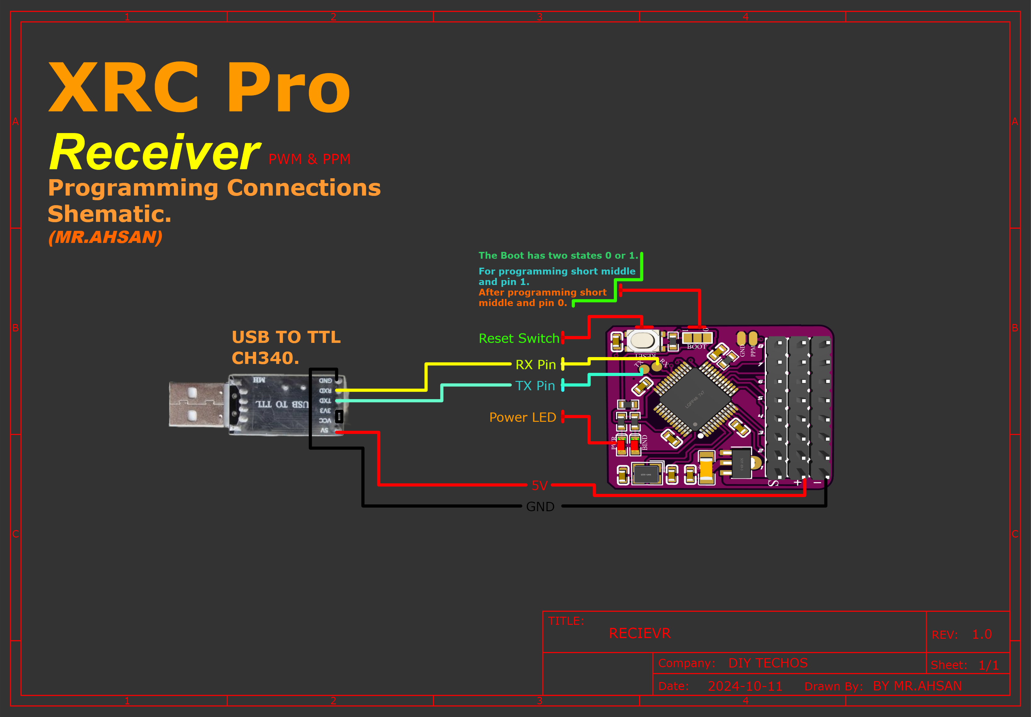
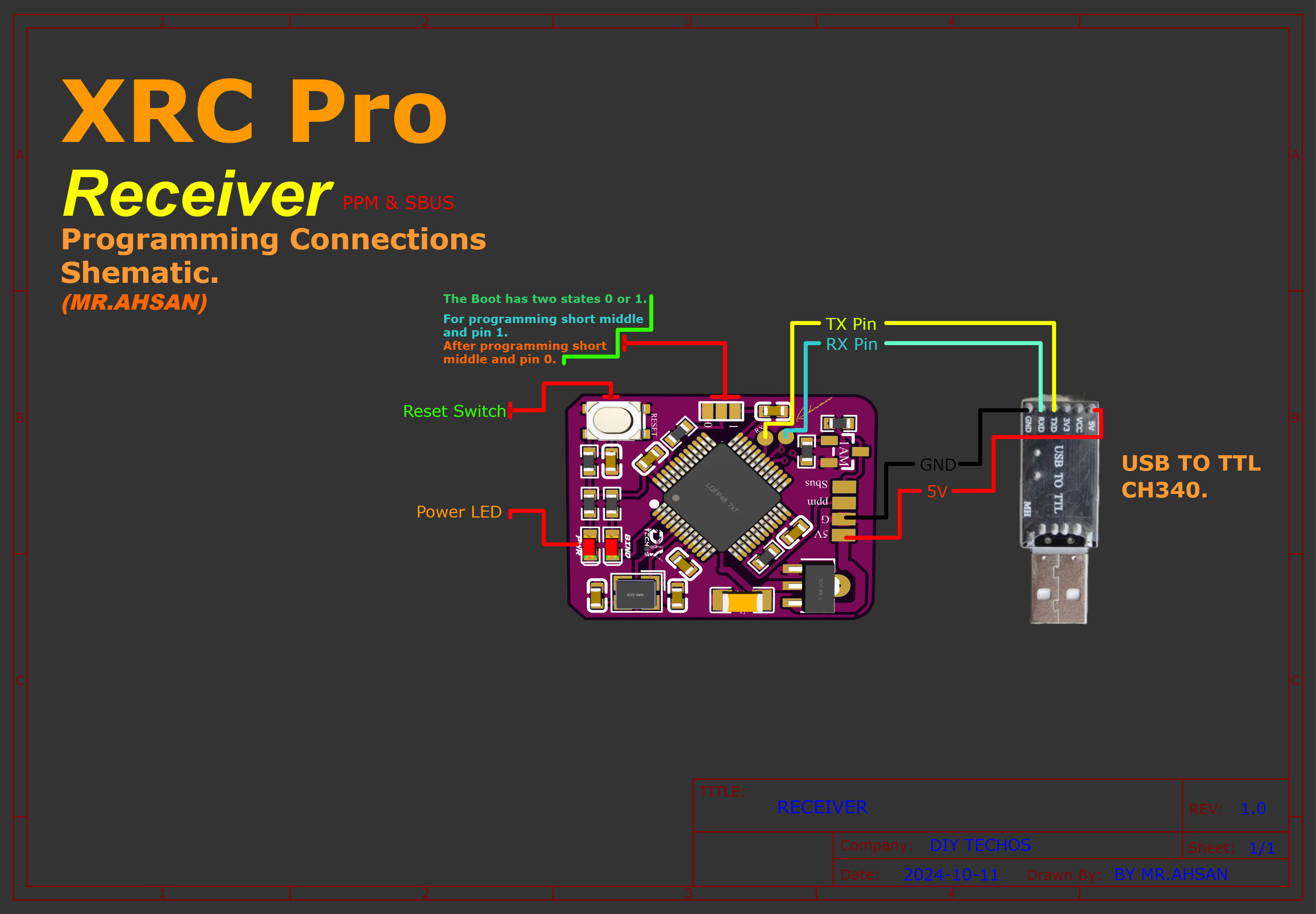
Step 4: Firmware Uploading
To upload the firmware to the transmitter and receivers, follow the connection diagram below. It shows how I connected the CH340 USB-to-TTL adapter to both the transmitter and receivers.
Connections
Transmitter
There are two methods of uploading code into transmitter.First,you can directly upload the code via USB TYPE-C Interface. Second,you can upload the code with the help of USBto TTL (ch340 driver).
Rceiver(PWM+PPM)
Receiver(PPM+SBUS)
Software
Download and install the STMicroelectronics Flash Loader Demonstrator software: Click to download
Steps
Follow:
Plug the USB serial converter into the PC.
Press the reset button on the STM32 board.
Select the COM port in the software.
Click 'Next,Next and Next.
Select Download to device.Click on 3 dots and select the hex file.
Select Global Erase.After that Click on Next
Within 15 seconds, the code will be uploaded to the device.


 2D and 3D Preview