What Are Current Transformers?
A current transformer is a type of instrument transformer used to measure alternating current, or AC, by scaling it down to levels suitable for metering instruments and/or protection relays. Using a current transformer is ideal when the insulation of a metering or protective instrument cannot withstand the line current without breaking down.
Construction
A current transformer consists of primary and secondary windings on a laminated steel core. Its most conspicuous feature is a small number of turns in the primary winding (one or two turns of thick wire with high current-carrying capacity) compared to a large number of turns in the secondary (several hundred turns of fine wire).
Consequently, a CT produces a current in the secondary winding that is proportional to that of the primary. An alternative construction, namely the ‘window-type’ current transformer, has an opening through its steel core. Through this passes a conductor, which carries the primary current.

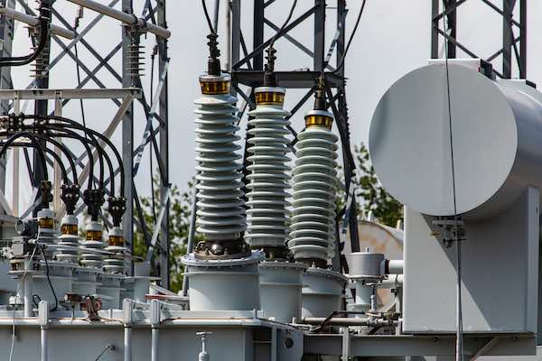
Current transformers (pictured in the middle) at an electrical substation.
Differences Between Current Transformers and Potential Transformers
Current transformers and potential transformers (PTs) are collectively known as ‘instrument transformers’. This is as they are designed to convert a high current/voltage into levels suitable for measuring and protective devices. However, there are several distinctions between the two transformer types.
A CT is used to scale a high current into a lower one, while a PT converts high voltage into a low voltage. In a CT, the primary winding has a much smaller number of turns relative to the secondary winding, while the opposite is the case in a potential transformer.
Functionally, this implies that the secondary current is proportional to that of the primary in a CT, and vice-versa in a PT. CTs have standard ratings of 1A or 5A, while PTs have standard ratings of 120V in the secondary for primary voltages up to 24kV, and 115V in the secondary for primary voltages exceeding 24kV.
CTs are also connected in series with a device, while PTs are connected in parallel. These arrangements allow current through the windings in a CT, while voltage appears across the windings of a PT.

A close-up of current transformers attached to copper busbars.
Selecting Current Transformers
Choosing the right current transformer ensures accurate measurements and suitability for metering devices. The following are some essential criteria for choosing a CT.
Transformation Ratio
CTs are specified using the ratio of turns in primary and secondary windings. For instance, (with ‘x’ standing for any number), x:5 current transformers and x:1 current transformers have amperages of 5A and 1A in the secondary windings, respectively.
The transformation ratio also describes the ratio of voltages in both windings. Transformation ratios can be calculated using a simple formula: Ip/Is (where ‘Ip’ = primary winding current and ‘Is’ = secondary winding current). The Is in most current transformers is either 1A or 5A, with most metering devices having the highest accuracy class at 5A.
Potential Losses
Making the right choice of CT also depends on the current rating of the measuring instrument or relay, as well as the conductor length between the device(s) and CT. The reason for this is that line losses increase at higher currents and longer spans. 5A CTs are ideal in cases where the measuring apparatus and transformer are less than 10 metres apart, while 1A CTs are preferable for longer cable spans to minimise line losses.
Accuracy Classes
Current transformers are also specified using precision classes, which describe the level of precision in measured current values. According to the IEC 61869-1 standard, the accuracy classes for current transformers are 0.1, 0.2s, 0.2, 0.5, 0.5s, 1, and 3. The following are some CT accuracy classes for different applications:
Class 0.1 or 0.2: Standard metering
Class 1: Industrial metering
Class 0.5 to 0.5S/0.2 to 0.2S: Utility metering
Class 5P or 10P: Protection metering

Power lines at an electrical distribution station.
Rated Frequency
Frequency, measured in Hertz, is a chief consideration when it comes to choosing a CT. As a general rule, the rated frequency of a CT must be equal to or greater than the frequency of the intended application. For example, a 50Hz or 60Hz CT is suitable for a 50Hz installation.
The Amperage of the Installation
Choosing the right CT also depends on the amps that are to be measured. For instance, the CT required for electrical loads of a single room will be smaller than that of a large building. For the most accurate results, the load amperage should be as close to the CT amperage as possible.
For instance, a 50A CT is fit for a 45A installation. Choosing a CT with a significantly higher amperage than the installation (e.g. a 50A CT for a 10A application may cause it to read ‘0A’).
Burden
The ‘burden’ of a CT refers to the amount of resistance (in ohms) and inductance (in mH) that can be connected to its secondary winding without causing a margin of error greater than specified by its accuracy class. Factors that make up the burden of a CT include the number of meters and relays, as well as the length of the conductor connected to the secondary winding.
The total effective burden on a current transformer is a combination of the burdens of each connected device in watts and VAR (volt-amps-reactive).
The Importance and Applications of Current Transformers
Current transformers are essential for isolating electrical devices from what is the higher utilisation current present in AC transmission lines. They work by scaling down the supply current to levels that are safe for metering and protection devices.
Key applications of CTs include electrical substations, commercial facilities, and industrial power distribution plants. CTs are similar to potential (voltage) transformers but they differ in terms of construction and operation.
Choosing the right current transformer assures its measurement accuracy. This requires one to ensure that the CT’s rated specifications match the intended operation—to minimise unwanted costs, energy losses, and equipment failure.