This article will discuss the basic concepts of circuit design and analysis. But first, let’s take a look at the basic elements of a circuit.
Basic Circuit Elements
At a high level, electronic circuits consist of three elements:
-
Power source: supplies AC or DC power to the circuit
-
Conductor: the medium through which electricity flows from the source to the load
-
Load: any element that consumes or dissipates energy. In practice, electrical loads can refer to the various components on a breadboard or PCB.

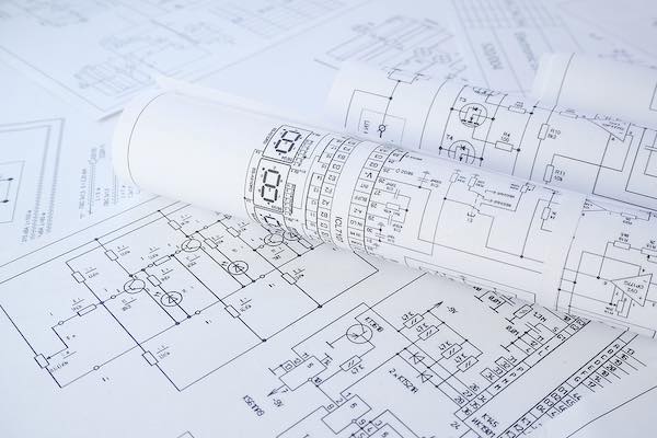
Printed drawings of electrical circuit schematics.
AC and DC Circuits
Depending on the nature of the power source, circuits can be AC or DC. The power source in an AC circuit delivers a periodically reversing current–graphically depicted as a sinusoidal waveform, while DC circuits have a unidirectional current with a pure sine waveform. AC circuits are utilized in high-power applications such as electric motors and power transmission networks, while DC circuits are typically utilized in low-power applications such as portable electronics and Battery management systems (BMS).
Analogue and Digital Circuits
Analog circuits are electronic systems having current and voltages that vary continuously over time, i.e., they transmit information in the form of time-varying, continuous signals. Analog circuits are one of two types–active or passive. Active circuits contain active components such as transistors and diodes, while passive circuits contain passive components such as resistors and inductors. A common application of analog signals is for instrumentation in medical treatment, such as in Electrocardiogram (ECG) signals.
Digital circuits utilize digital signals that consist of two discrete levels. Both levels represent different “states,” such as 1/0, ON/OFF or True/False. They often contain transistors that create logic gates using Boolean logic. Logic gates are the building blocks of integrated circuits (ICs) utilized in today’s electronic devices such as notebook computers, smartphones, and appliances.
Designing Circuit Schematics
Circuit schematic drawings are symbolic representations of electric circuits that can be drafted on paper or in digital form (using a PCB design software such as EasyEDA). A circuit schematic shows the various components (using standard electronic symbols) and their interconnections. These designs are conventionally organized from left to right of a page.
To design a circuit schematic using PCB software, you may start with a basic circuit template. From a panel within the application (which may be labeled “symbols” or “tools”), you can choose from a variety of electronic components such as capacitors, inductors, resistors and more. Pick and place components at various points of the circuit as required, and link them using connecting lines. You can also increase the complexity of your circuits by creating additional layers using PCB floorplans.
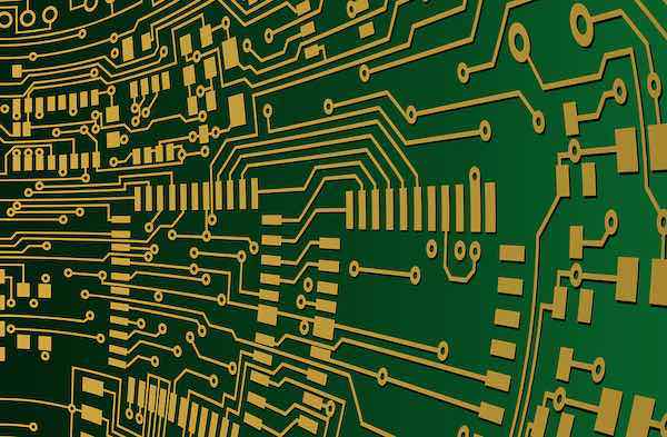
A close up of circuit traces on a finished PCB.
Testing and Verification
Within the PCB software environment, you can test your designs by adjusting various circuit parameters–such as applying DC or AC power to an element or changing the values of resistors. If your design is accurate, the system should run as intended, and give an output similar to what you would obtain from calculations.
To troubleshoot electrical problems (verification), you can check for errors in your design by running an electrical rule checker (ERC). For design problems, most software tools feature a design rules checker (DRC). The DRC verifies whether or not your design is congruent with the geometrical constraints of the target PCB. For example, it checks for minimum trace widths, the spacing between traces, pads, and through-holes, and verifies that analog and digital circuit grounding is kept separate. Once your schematic is complete, you can convert it into a layout to fabricate the final PCB.
Electrical Circuit Analysis
Circuit analysis is the process of finding the voltages and currents in each element of an electronic circuit. The purpose of this is to solve problems in electric circuits using an established set of equations. Two popular methods for circuit analyses are the node voltage method and mesh current method. Both rely on Kirchhoff’s and Ohm’s laws.
Node Voltage Method
The node voltage method (aka nodal analysis) uses Kirchhoff’s current law and Ohm’s law to determine voltages between nodes (points in a circuit where two or more elements connect).
According to Ohm’s law, the value of current flowing through any two points in an electronic circuit is directly proportional to the potential difference (aka EMF) between the two points. Mathematically, this is expressed as V = I/R (where v is the voltage in volts, I is the current in amperes, and R is resistance in Ohms).
Kirchhoff’s current law (KCL) states that the current flowing into a node and out of a node at any given time is equivalent. Mathematically, this is expressed as IOUT = IIN or - IOUT + IIN = 0.
The basic steps involved in Nodal analysis include:
-
Selecting a reference (or ground) node and defining its value as 0V
-
Using notations such as nodes a, b, c, etc. to define all other nodal voltages
-
Using KCL to find the nodal voltages around the circuit
-
Solving for the nodal currents using Ohm’s law

Electronic circuits are the subtle powerhouses behind all modern devices and equipment. Image Credit: Pixabay.
Mesh Current Method
The node voltage method uses Kirchhoff’s Voltage Law (KVL) to find the value of current flowing around loops in the circuit. KVL states that the algebraic sum of all the voltages in a loop is zero. Mathematically, KVL can be expressed as ∑ (I1 + I2 + I3) = 0.
The mesh current method is based on the concept of loops and meshes. A loop is any closed area around the circuit starting from the terminal of any component, around connected elements, and back to the starting point. A mesh is a loop that doesn’t contain another loop.
To find the currents flowing around loops with the mesh current method:
-
Find the meshes within the circuit
-
Assign current notations to each mesh, working in a clockwise or anticlockwise direction
-
Write KVL equations for each mesh
-
From the resulting equations, calculate the mesh currents.
Electronic circuits of varying complexities are present in every kind of equipment or device that improves the quality of human life. The role of electrical engineers is to design and analyze these circuits wherever they are found to ensure normal working conditions and minimal downtime.