Troubleshooting is the process of identifying problems in malfunctioning equipment and applying corrective measures to return them to their optimal operation. Engineers achieve this by testing the various components either individually or collectively to isolate faults that occur while using the product in question.

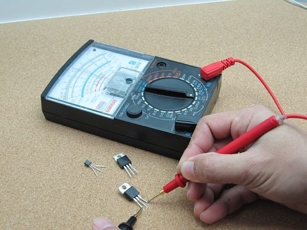
An electrical engineer’s first-person view as they test the electrical properties of a transistor. Image Credit: Pixabay.
What Causes Failures in Electrical Equipment?
A great place to start troubleshooting faulty equipment is by determining what the most likely causes of the failure are. Equipment failures can be classified in several ways, such as functional failures and failures due to operating conditions. There are plenty of examples of the latter, some of which are covered in the next few sections.
Over Temperature/Heating
Except for components that are engineered for heat resistance, high ambient temperatures can have a destructive effect on various circuit components. In some devices, overheating can occur when the primary cooling system fails (e.g., an active heat sink and cooling fan in a laptop).
Extended Use
Electrical equipment that is extensively utilised (especially beyond their specified lifetimes) will eventually have failed components. Moreover, many devices that have been long relied on in industrial environments, which have both high temperatures and vibration, can eventually succumb to internal component damage due to overheating and mechanical shock.
Short Circuits
Bridged terminals brought on by moisture, rusting, and/or broken-down insulation can cause excessive current flow through electric circuits, ultimately causing a short circuit. Short-circuiting causes overheating, which can lead to electrical fires and/or explosions.
Overcurrent and Overvoltage
Overcurrent occurs when the current that flows through a conductor is greater than its maximum-rated current. Common causes are ground faults, overloading, and short circuits.
Similarly to the self-explanatory ‘overcurrent’, overvoltage occurs when the voltage within an electric component exceeds its maximum-rated voltage. For instance, when a 220 to 240V-rated appliance receives 350V from a power source, it is of course in an overvoltage condition.
Common causes of overvoltage are power surges, electric arcs, and inadequate insulation. In situations where the supply voltage is far greater still than the maximum operating voltage, the existing insulation even breaks down, leading some current to begin leaking through.
Failure Modes
Failures can occur at any point between the beginning and end of the useful life of an electronic product. Failure modes refer to the number of ways that a part can fail functionally, which is usually limited. Common failure modes include:
-
Mechanical failures (consider fractured components, damaged electromechanical contacts due to high mechanical stress conditions, and so on)
-
Failure due to corrosion (one of the many examples of this involve rust and mineral deposits that form on metallic contacts and/or terminals)
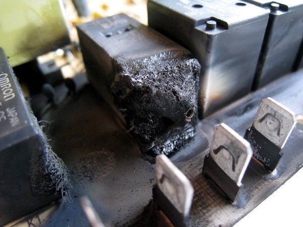
An example of extreme electrical component damage: a burned electromechanical relay. Image Credit: Pixabay.
Electronics Troubleshooting Techniques
Electric circuits comprise several discrete components that may fail as the product approaches the end of its lifecycle. The following techniques are useful for resolving problems and ultimately having them function properly again.
Physical Inspection
Performing a detailed physical inspection of electrical equipment is vital to identify defects, rust, cracks, chips, and other kinds of damage to internal components. Engineers often examine parts against a checklist to standardise the procedure. Visual inspection also allows engineers to spot bridged terminals, loose wiring, broken-down insulation, and worn electromechanical contacts, etc., which may result in open/short circuits and other faults.
Testing Passive Components
Passive components (such as resistors, diodes, and capacitors) control the behaviour of electric circuits. Faulty or damaged components can cause several fault conditions. Engineers can test and isolate failed passive components using a multimeter, and such components can be tested while connected to the rest of the circuit (or first, de-soldered).
Testing Circuit Protection Devices
Blown fuses, defective relays, or tripped circuit breakers help to isolate electrical equipment from a power source during abnormal conditions. An appliance that won’t turn on may be due to the failure of one or more circuit protection devices. Multimeters can test for blown fuses by checking for continuity between the terminals. (Note that breakers and relays should be returned to their ON/closed positions before the multimeter is used to check for continuity.)
Testing Functional Areas
Electric devices are composed of several functional areas, such as power supply, processors, signal lines, and so on. By testing functional areas separately, engineers improve the accuracy of fault detection. Sections identified with defective components should be isolated immediately.
Troubleshooting Conductors
The said continuity function of a multimeter can be used to test the condition of connecting wires. The multimeter will give off a beeping sound and/or display infinite resistance (the OL—namely the ‘Open-Loop’ reading) when its probes are connected between any two sections of the wire. Such signals indicate that a good conductor is in use.
Signals Testing
Oscilloscopes (see example above) and logic analysers are used to test the behaviour of digital circuits. These devices generate the data of circuit parameters and display them graphically on the interface in question. Such output data can be used to localise faults within an electric circuit.
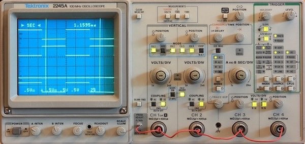
An oscilloscope (Tektronix 2245A). Image Credit: Pixabay.
What Tools Do Engineers Require for Hardware Troubleshooting?
The tools required for troubleshooting electronic hardware are mostly test equipment for circuit parameters and/or signals.
Digital multimeter: multimeters are a particularly vital piece of test equipment. They can test for several circuit parameters, such as current, voltage, and resistance. Multimeters are also able to measure voltages up to 50VDC/250VAC. Note that currents ranging from 250mA to 10A are ideal for troubleshooting most circuits.
Oscilloscope: an oscilloscope is an electronic test instrument used to graphically visualise and analyse waveforms generated by electric circuits. It’s thanks to such generated output that engineers can more easily isolate faulty sections of the devices.
Logic analyser: a logic analyser is used to capture and display multiple signals from digital circuits. The output can be used for fault detection (for example, in integrated circuit testing).
Documentation: product documentation supplied by the manufacturer is invaluable for effective troubleshooting. Examples are circuit schematics, power distribution diagrams, part numbers (for the replacement of failed components), and even troubleshooting software.
All in all, while every electronic product is ultimately bound to fail—even when they’re properly handled and used—hardware troubleshooting (such as in the examples above) allows both engineers and hobbyists to identify, and potentially fix, electrical faults.
Indeed, by having adequate knowledge of the root causes of electronic component failure—coupled with the right test equipment and procedures, of course—engineers can maximise their products’ useful lives and therefore save costs on replacements.