Why Should Engineers Use PCB Design Tools?
Electrical engineers and designers enjoy several benefits from using software tools for their PCB designs. The following are the most significant:
Reductions in Design Complexity
The most essential benefit of using PCB design software is the simplification of design complexity. Using industry-recognised notations, schematics, and dimensions, users can design circuits on single-layer or multiple-layer boards that have very many components—while encountering minimal errors.
Reductions in Production Times and Time to Market for New Products
Most PCB design software comes with easy-to-use interfaces with electrical templates that designers can build on to shorten production times and the time to market (aka TTM) for new products. Engineers can simply pick and place electronic components in a 3D environment or alternate between various designs to find an optimal model.
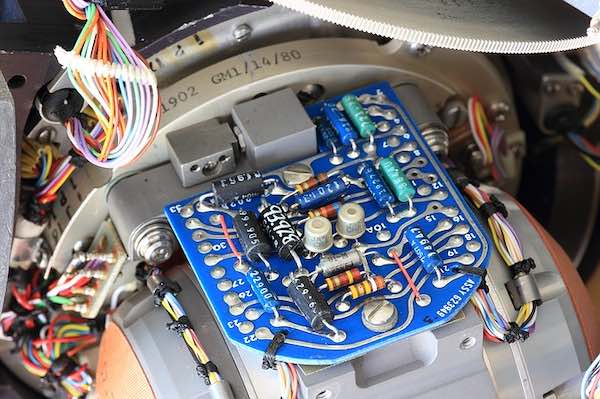
Printed circuit board (for the Litton LnLN-3 inertial navigation system), alongside other corresponding electronic components. Image Credit: Pixabay.
Savings in Costs on Production
PCB design software can help save production costs that would otherwise be spent on physical prototypes. Rapid virtual prototyping through the use of software tools allows manufacturers to only commit labour and resources to the most cost-efficient, optimal model for the final product.
Minimisation of Design Errors
Electronics design software automatically checks for errors and verifies electrical and physical design rules, such as gap and trace widths, separation, layout, and so on. At every phase of the design, it highlights the errors, for the users to quickly act on; plus, the software also allows a user to check the final design against the original schematic for congruency.
How to Choose the Best PCB Design Software for Your Projects
Given the vast number of PCB software available online (both free and paid), it may well be overwhelming to select the best program for your needs. To choose the right PCB design software, it’s best to keep an eye out for the following qualities:
-
User-friendliness: the best PCB design software should be easy to navigate, even for relatively inexperienced designers. Intuitive software should contain design templates, tools, and a comprehensive library of components. User-friendly guides are also useful for walking new users through the software. On the other hand, non-intuitive software relies heavily on documentation like hard or softcopy manuals to enlighten users about the software.
-
Essential features: the best PCB design software provides a host of features for managing both simple and complex designs. A word of caution here is that feature-intensive software takes up a considerable amount of memory, so it might help to look out for those that store cloud-based data, so to free up local space.
-
Comprehensive libraries: electronics design software that have extensive libraries contain most of the components that engineers use in their designs. This makes them future-proof and helps to minimise errors from unsupported components during design verification.

A printed circuit board and its circuit components. Image Credit: Pixabay.
Top 5 PCB Design Software for Electrical Engineers
With the above qualities in mind, choosing the best software for your needs should be easier. Below are our 5 leading electronic design tools for engineers:
KiCAD
KiCAD EDA is an open-source PCB design and automation suite for designing circuits on any board size. It has a user-friendly and intuitive user interface which simplifies the design process. KiCAD provides features such as schematic capture, PCB layout, and a 3D viewer with extensive documentation, software libraries, and repositories.
EasyEDA
EasyEDA is an open-source and subscription-based online electronics design tool that incorporates schematic capture, PCB design, libraries design, project management, and team collaboration. It provides PCB design features, such as footprint manager, dimension check, audio router, version control, 3D view, and so on. EasyEDA provides access to over 200,000 real-time components that users can purchase from LCSC, China’s leading electronic components online marketplace.

The reverse side of a printed circuit board, which shows the conductive traces. Image Credit: Pixabay.
DesignSpark PCB
DesignSpark PCB (from RS Components) is one of the best-known, free-to-use electronics design software for engineers. It contains a host of features for rapid prototyping, testing, and electronic rules verification; plus, it has easy integration with other aspects of product design workflows. Like KiCAD, DesignSpark has no limits on board size and it allows users to create unique PCB part libraries, import and/or export their Gerber design files, and generate bills of materials (BOMs) in multiple formats.
TinyCAD
TinyCAD is another great, open-source circuit design tool that is free-to-use. The application is available as a secure online download from SourceForge and is written in C++. TinyCAD supports common PCB layout formats, such as standard netlists formats and Simulation Program with Integrated Circuit Emphasis (aka SPICE). It has a user-friendly interface and tools to reduce design complexity.
PCBWeb Designer
PCBWeb Designer is a simple-to-use, yet professional electronics design tool that is available as a desktop application. It is one of the most widely-used software in the electronics design community. The software provides schematic capture, PCB layout tools, Arrow part catalogue, and a BOM manager. Moreover, when they’ve finished designing, engineers can order the components they need from DigiKey through the BOM manager.
Ultimately, electrical (and of course electronics) engineers should be well-equipped to utilise software tools to simplify design complexity, speed up the production process, and minimise errors in electronic design. Whether you want your software to be free or paid-for, web-based or desktop-based, and so on,, suffice to say any of the above-listed products will do the job efficiently.
