What is an Electric Circuit?
In the simplest terms, an electric circuit is a pathway for an electric current to flow from one point to another. From a high level, every circuit has three basic components:
-
Voltage source
-
Conductive path
-
A Load
Voltage Source
A voltage source introduces energy into a circuit via a potential difference between its positive (+) and negative (–) terminals. Voltage sources can be AC or DC–the main difference being how the current flows. AC sources produce voltages that vary sinusoidally, i.e. the current reverses direction periodically. Examples are power from the grid or generators. On the other hand, DC sources produce current that flows in one direction. Batteries are a source of DC voltage.
Conductive Path
A conductive path (aka a conductor) provides a medium for current flow through a circuit. These components have a very low resistance to current, e.g., copper wires, lead solder, or metallic traces on a printed circuit board (PCB). Conductors also help link other components together to achieve a single function.
Load
A load is any device that consumes power in a circuit. It can be anything from a light-emitting diode (LED) to a motor or siren. During a short circuit, the load is the conductor itself which generates heat, dissipating electric power.
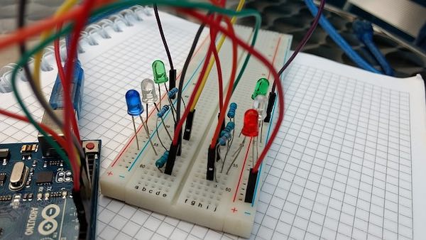
Electronic components on a breadboard. Image credit: Pixabay.
Electric Circuit Analysis: Types of Components
An electronic component is an element within an electronic circuit that affects the flow of current or electromagnetic fields. Many modern circuits comprise passive, active, and electromechanical components.
-
Passive components are elements that consume electric power without introducing any net energy into a circuit. Common examples are resistors, capacitors, and inductors.
-
Active components control the flow of current in electric circuits. These elements may amplify current, inject it into a circuit, or produce a power gain. Transistors, thyristors, and triode vacuum tubes are all active components.
-
Electromechanical components are components that utilize electric current or voltage in a circuit to perform a mechanical function, e.g., DC motors or relays. In the case of electromechanical solenoids, voltage is used to actuate a set of mechanical contacts by varying the inductance in its coil.
Electric Circuit Analysis: Circuit Parameters
Current and voltage are the most essential parameters of electric circuits. Similarly, resistance, inductance, and capacitance are vital attributes of electronic components.
Current
Electric current is the flow of electrons through a circuit. The unit of measurement for current is Ampere (A). As we discussed earlier, the current can be AC or DC.
We can find the value of current flowing through a circuit using Ohm’s law which states that the current between any two points is proportional to the potential difference between them.
The equation is I = V/R (Where I is current, V is voltage, and R is resistance).
Practically, we can obtain the value of current in a circuit using a digital multimeter.
Kirchhoff’s Current Law (KCL) for Electric Circuits
According to Kirchhoff’s current law, an electric current always flows in loops around a circuit, i.e. it starts and ends at the same point. Also, the value of current entering the circuit is the same as that leaving the circuit (1). Similarly, the sum of all the currents entering and leaving the circuit per time is zero (2). We can express these statements mathematically using these equations:
IIN = IOUT ---------------------------- (1)
IIN + (-IOUT) ---------------------------- (2)
Voltage
Voltage (V) sometimes referred to as Electromotive force (E) is the potential difference between any two points in an electric circuit. The unit of measurement is the Volt. Like a current, the voltage can be AC or DC.
Voltage can also be derived from Ohm’s Law using the formula V = IR (Where V is voltage, I is current, and R is resistance).
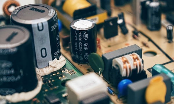
Passive components. Image Credit: Pixabay
Kirchhoff’s Voltage Law (KVL) for Electric Circuits
According to Kirchhoff’s voltage law, the sum of voltages around closed circuits is always zero, i.e., ΣV = 0. We can express this mathematically as:
V1 + V2 + V3 + ……Vn = 0 ---------------------------- (3)
Resistance
Resistance is the attribute of a component to resist the flow of electric current through a circuit. The unit of measurement is Ohms (Greek symbol: Ω).
According to Ohm’s Law, the resistance of a conductor is the ratio of voltage (V) flowing across it to the current (I) flowing through it. Mathematically, R = V/I (Where R is resistance, V is voltage, and I is current).
Every component (except superconductors) offers varying levels of resistance. However, resistors are designed especially for that purpose. They are two-terminal, passive components having varying resistances. Some resistor types are marked with color codes to indicate the resistances and tolerance they offer.
Inductance
Inductance is the tendency for a magnetic field to be induced in a conductor when an electric current flows through it. The strength of this induced magnetic field is proportional to the magnitude of the current. The unit of measurement for inductance is Henrys (H), named after Joseph Henry, the American scientist that discovered it.
Inductors, aka chokes or coils, are simple passive components that can store up energy in magnetic form when electric current flows through them. They consist of a conductor wound into a coil which generates a magnetic field in the opposite direction when an electric current is applied.
We can calculate the inductance in an electric circuit using the formula:
L = V/(di/dt) (Where L is the inductance, V is the potential difference across the coil, and di/dt is the rate of change of current in A/s).
Capacitance
Capacitance is the ability of a circuit element to store an electric charge when a potential difference exists between its terminals. The unit of capacitance is the Farad, named after Michael Faraday, the scientist that discovered electromagnetic induction.
To determine the capacitance of a component in an electric circuit, we can use the formula:
C = Q/V (Where C is the capacitance in coulombs, Q is the charge, and V is the potential difference).
So far, we have attempted to cover some of the most essential aspects of electric circuit theory. Today, electronic systems are becoming increasingly complex as more elements are integrated into component-dense substrates. Nonetheless, the basic principles underpinning them remain unchanged.