While building electrical and/or electronic systems and devices, electrical engineers utilise a variety of testing equipment to measure common system parameters, such as current, resistance, voltage, and capacitance. Additionally, they can test for special circuit variables like digital and analogue signals, frequency, and so on.
The below covers some essential testing gear that every electrical engineer should have.
Basic Testing Equipment for Electrical Engineers
Digital Multimeter
A ubiquitous device found in virtually every electrical engineering lab, multimeters function as combined ammeters, ohmmeters, and voltmeters—to test for current, resistance, and voltage respectively. A multimeter can also serve the following 3 functions:
Testing Coils
You can use a multimeter to test the condition of an ignition coil by touching the test probes of the device to the positive and negative terminals on the primary and secondary ignition circuits. Ignition coils typically have an inductance anywhere from 0.4Ω to 2Ω in the primary circuit.
A zero-value reading means that the coil is shorted and a reading greater than the manufacturer’s specifications signifies the defectiveness of the coil and that it needs to be replaced.
In the secondary circuit, the nominal reading is between 6KΩ to 10KΩ (or otherwise as specified in the manual) for a working coil. Just as is the case in the primary circuit, a zero-value result means that the secondary coil is shorted. Further, a significantly higher reading indicates a coil that is defective altogether.
Testing Diodes
Some digital multimeters can test diodes in forward-bias if they contain a diode function; or they can test indirectly by monitoring the diode in resistance mode. To test a diode in diode function, the multimeter applies a small voltage between the test probes and measures the voltage drop across them.
To test a diode that is connected in a circuit, be sure to first discharge the capacitors, as they may hold residual voltage. Then, set the device to the diode function and connect the test probes to the corresponding diode terminals.
A forward-biased silicon-based diode that is in good condition will display anywhere from 0.5 to 0.8V (0.2 to 0.3V for Germanium-based types) and OL (overload) when it is reverse-biased. A bad diode will display OL in both the forward-biased and reverse-biased conditions, whereas shorted diodes feedback about 0.4V in both bias directions.
Checking Continuity
Continuity is a simple but effective test for checking open and closed-circuit conditions. To determine current flow through a circuit, set the multimeter to the continuity function (which is often displayed as a ‘beeper’ icon) and connect the test probes to the negative and positive terminals, or otherwise any two sections of a bare conductor.
If the circuit is continuous, the device will emit an audible and sustained sound until the probes are disconnected.
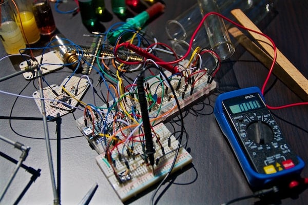
Electrical circuit boards near a digital multimeter. Image courtesy of Pexels.
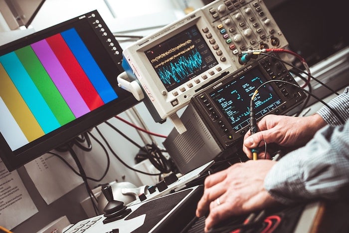
Electronics Test Bench
An electronics test bench is an assemblage of electronic test equipment for electronic components and circuits. A test bench may contain a multimeter, AC/DC power supplies, a digital oscilloscope, soldering stations, and other accessories depending on the level of sophistication of the device under test (DUT).
Electronic and/or electrical engineers and designers utilise test benches of varying configurations to test and verify input/output from PCBs, RF devices, robots, and more.
Arbitrary Waveform Generator
An arbitrary waveform generator (AWG) is a piece of electronic test equipment used to generate repetitive or single-shot (non-repetitive) waveforms for signal analysis and processing. They can analyse and model the signals produced by other devices, such as digital and mixed-signal oscilloscopes.
AWGs are used to design, test, or troubleshoot electronic, electrical, and electro-acoustic systems. For example, they can be used to apply incident (reference) signals to electrical cables in the time-frequency domain reflectometry (TFDR) technique to estimate the remaining life of cross-linked polyethylene (XLPE), ethylene propylene rubber (EPR), and silicone rubber (SIR)-insulated cables.
A digital signal oscilloscope. Image courtesy of Bigstock.
Digital Frequency Counter
A digital frequency counter (DFC) is an electronic test device used for measuring frequencies by counting the number of oscillation cycles (pulses per second) produced by an RF device.
A frequency counter works by recording the number of times a signal passes through a voltage (trigger) point within a specific time (known as a ‘gate period’). For example, if the device is set to count frequencies per second, and a waveform passing the trigger point 50 times, then the frequency count is 50Hz.
DFCs are generally high-precision devices available in most electronic shops and online marketplaces for a budget price. Electrical engineers will find them particularly useful when designing and testing RF applications. Some examples include measuring the frequency of oscillators, transmitter carriers, and signals on a transmission line.
Finding the Best Test Equipment for Your Needs
As discussed, test equipment is vital for any electrical and/or electronic project. However, with the bevy of products on the market, it might be challenging to identify the best quality equipment.
As a rule of thumb, it’s best to buy electronics from renowned or reliable suppliers of course. Buying the best tools, however, may quickly become a trade-off between price and quality. It’s up to the engineer to find a product that satisfactorily meets both considerations.