What is Hardware Description Language?
A hardware description language is a programming language used for modelling the behaviour of a digital system.
Processes Involved in Digital System Synthesis Using HDL
Engineers meticulously follow certain procedures to successfully fabricate and manufacture digital systems. These procedures involve the use of electronic design automation (EDA) tools to achieve design specification and verification for small and large digital system designs.
The applications of such EDA tools in digital system synthesis are discussed in the next sections.
System Description
The first process involved in manufacturing digital systems using HDL requires the electronics engineer to break down the different parts of the system, thus enabling a good description in terms of both its behavioural parts and functionality.
Digital systems designs are often described at the level that specifies the system registers and transfer of data (namely through buses) between registers. The system description of registers can be achieved through register transfer level (RTL).
EDA tools such as Verilog provides RTL design techniques. Engineers can use procedural statements, continuous statements, and instantiation statements to describe data flow in registers.
Test for Functionality
After a system has been described, the functionality is tested to ascertain whether it has met system specifications. EDA tools can be used for this process via a testbench. Testbenches allow engineers to detect description errors and incompatibility of components used in the design.
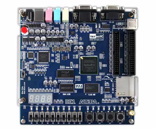
A product image of the Intel ALTERA DE1 board for FPGA applications. Image Credit: Intel.
Design Validation
Design validation involves a pre-synthesis simulation. Engineers do the pre-synthesis simulation by generating test data using EDA tools. For instance, Verilog simulation environments generate test data from testbenches. The pre-synthesis simulation doesn’t consider glitches and timing issues of the system. The pre-synthesis simulation is carried out using a functional simulator.
Furthermore, the design validation process can be done through assertion verification where an assertion monitor is used to continuously check the validity of design specifications while the design is being simulated. Open verification library provides assertion monitors for the design validation process.
Another process involved in design validation is formal verification. Formal verification is carried out to make sure a system behaves in accordance with the sets of properties designed for it.
Optimisation
To make a reliable and efficient digital system, it is important to eliminate redundancies in the components used in the design. Logic optimisation involves removing redundant logic expressions contained in the boolean expression of the design. This helps reduce the number of components used for the design to perform efficiently and reduce latency issues.
Synthesis
Synthesis is carried out to generate hardware from a design description made by the engineer. Once they have verified the design specifications and the pre-synthesis simulation results, it is then time for compilation. The design will be compiled in accordance with the target hardware for which it is designed.
Examples of target hardware include an application-specific integrated circuit (or ASIC) and field-programmable gate array (FPGA). During synthesis and compilation, timing and functional specifications are made available for analysis and verified if they are compatible with the target hardware. Such a process is also known as binding.

An electrical circuit featuring custom integrated circuits.
Routing
Routing is simply done to place the design on FPGAs or ASICs. This process involves dealing with the wiring and interconnections of the design modules on the target hardware.
Post-Synthesis Simulation
In post-synthesis simulation, a generated netlist is simulated. Also determined are the timing details, clock speed or frequency, and worst-case delays of data transmission from one component to another. This process is done by the engineer to make sure that any glitches in the system are eliminated.
Once the post-synthesis simulation test is passed after compilation on the target hardware, the design is completed.
Environment Design Automation Tools Used in HDL
Engineers achieve the above-mentioned procedures by using electronic design automation languages such as Verilog and Very High Speed Integrated Circuit Hardware Description Language, aka VHDL. These two languages are officially endorsed by the Institute of Electrical and Electronics Engineers.
Verilog enables engineers to do switch level modelling, including unidirectional and bidirectional switches. It also features charge storage modelling, which makes it possible to describe dynamic complementary metal oxide semiconductor (aka CMOS) circuits. In addition, Verilog provides bussing specifications for digital systems that have registers. It also provides various timing control constructs.
Testbench generation, test data generation, data handling, and other system utilities are featured in Verilog. Read and write operations are also possible using such a tool.
Generally, HDL enables engineers to design reliable digital systems. With HDL, the speed and the complexity of digital circuits have increased rapidly. It also makes the realisation and synthesis of digital circuits easy, given that engineers design at the register transfer level. What’s more, troubleshooting and debugging is also easy for the design of digital systems using hardware description language.
