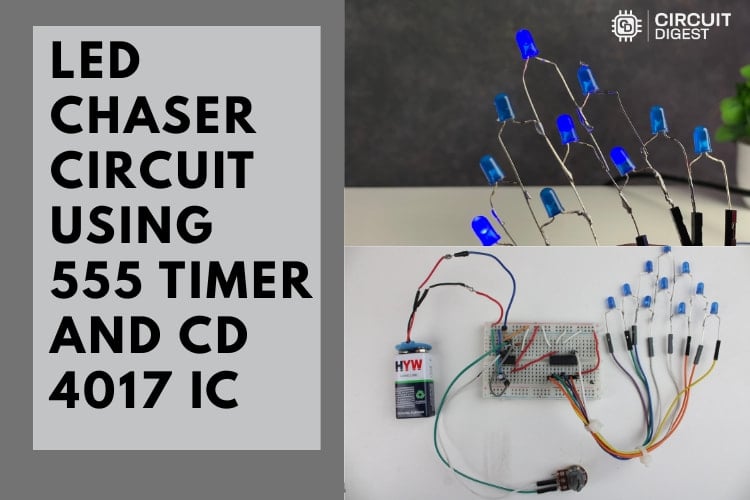
Build a fun, adjustable LED chaser using a 555 timer and CD4017 decade counter — ideal for beginners, decorative lighting, and hands-on electronics learning.
Introduction
The LED chaser circuit is a classic electronics project that produces a visual “running light” effect by lighting a sequence of LEDs in succession. This effect is created using two affordable and beginner-friendly ICs: the 555 timer and the CD4017 decade counter. With just a handful of components, you can build an eye-catching chaser for decorations, learning labs, or maker demos.
What You’ll Build
In this project, the 555 timer IC is configured as an astable oscillator, producing a steady stream of clock pulses. These pulses are fed into the CD4017 counter, which turns LEDs on one at a time in sequence. Adjusting a potentiometer changes the pulse speed — and thus the pace of the LED chase.
Understanding the Key ICs
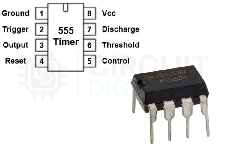
555 Timer (Astable Mode)
The 555 timer acts as the heartbeat of this project. In astable mode, it continuously toggles its output between high and low, creating a square wave (a clock signal). The frequency of these pulses is controlled by resistors and a timing capacitor — and by changing the potentiometer value, you change how fast the LEDs chase.
Key 555 Pins in This Project:
- Pin 3 (Output) — Sends clock pulses to the CD4017
- Pin 2 & Pin 6 — Connected to the timing components
- Pin 4 (Reset) — Held high to avoid unexpected resets.
- Pin 1 & Pin 8 — Ground and Vcc respectively.
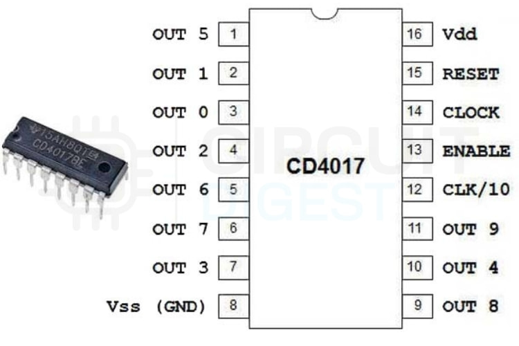
CD4017 Decade Counter
The CD4017 is a 10-output decade counter. For every rising pulse received at its clock input, it activates the next output pin in order — from Q0 to Q9. Each output drives one LED, so only one LED lights at a time. Once Q9 is reached, the sequence loops back to Q0.
Important CD4017 Connections:
- Pin 14 (Clock Input) — Receives pulses from the 555
- Pins 1–7, 9–11 (Outputs Q0–Q9) — LED drivers
- Pin 15 (Reset) — Tied low for continuous counting
- Pin 13 (Clock Enable) — Held low so counting isn’t disabled
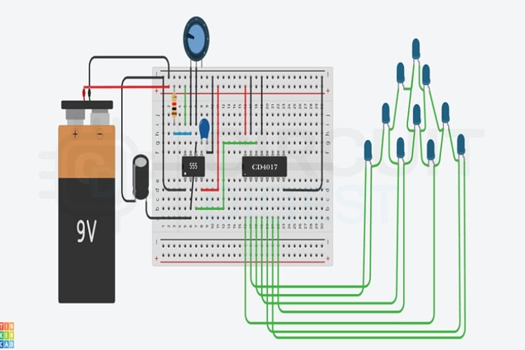
Building the Circuit
Power Setup:
Connect your power source (5–12 V) to the breadboard rails. Ensure the negative rail is grounded.
555 Timer Assembly:
Insert the 555 IC and place the timing resistor, potentiometer, and capacitor according to standard astable wiring.
Connect to CD4017:
Tie the 555 output (pin 3) to the CD4017’s clock pin (pin 14). Ground the CD4017 reset (pin 15) and clock enable (pin 13).
LED Array:
Connect each CD4017 output pin to its own LED (through current-limiting resistors) arranged in a row.
Decoupling:
Place a small 0.1 µF capacitor close to both ICs between Vcc and GND to stabilise the supply.
Final Testing:
Power up and adjust the potentiometer to see how the LED chase speed changes.
How It Works (Simplified)
- The 555 timer continuously generates pulses.
- Each pulse advances the CD4017 counter to the next output.
- Only one LED is lit at a time, creating a smooth “chasing” effect.
- When the counter reaches its last output, it loops back to the start.
- The potentiometer varies the timing resistance, which changes the 555’s pulse rate. Circuit Digest
Tips & Troubleshooting
- LEDs flicker or don’t sequence properly? Ensure all grounds are solid and decoupling capacitors are in place.
- All LEDs stay dim or don’t chase? Check that each LED has a resistor and that the 555’s output is correctly feeding the CD4017.
- Chase speed doesn’t change? Confirm correct potentiometer connections and timing capacitor orientation.
Enhancements You Can Try
- More LEDs: Cascade a second CD4017 for expanded sequences.
- Reverse Chaser: Use logic or a microcontroller to create bidirectional chase patterns.
- Sound-Interactive Mode: Replace the 555 clock with an audio-responsive trigger for music-synced lighting.
Conclusion
This LED Chaser Circuit with 555 Timer IC is more than just a pretty light sequence; it’s a practical way to learn timing circuits, counters, and creative electronics design. Whether you’re a beginner or maker hobbyist, it’s a rewarding build that invites further experimentation and learning.