This project involves Design and implementation of an universal battery charger capable of adapting to different battery technologies, chemistry and for type charging evaluation. The system is based on the Microchip PIC16F13145 and integrate CLC and CLB features for advanced safety and monitoring capabilities.
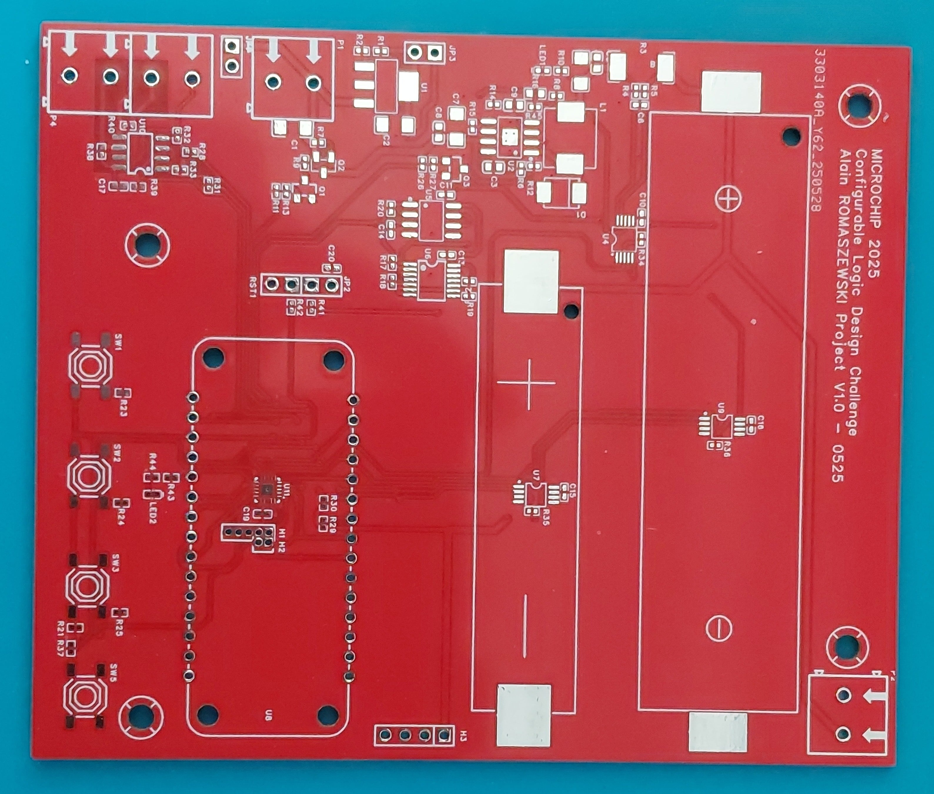
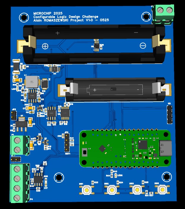
general schematic of the developed PCB
Overview
This project involves the design and implementation of an intelligent and universal battery charger capable of automatically adapting to different battery technologies (Li-ion, Li-Po, Na-ion,LiFePO4, etc.). The system is based on the Microchip PIC16F13145 microcontroller and integrates advanced safety, monitoring based on CLC, CLB feature and communication via modbus.
I think what the Configurable Logic Block (CLB) system from Microchip represents an innovative approach for implementing critical safety functions in industrial applications. Here's why this technology is particularly valuable:
Fundamental Safety Principle
The CLB enables the creation of programmable logic circuits that operate independently from the main processor. This physical separation is crucial as it ensures safety functions continue operating even in case of main software failure or microcontroller crash.
Advantages for Industrial Safety
Hardware Independence: Safety functions execute in a dedicated logic block, completely isolated from the main program. If the firmware freezes or enters an infinite loop, the protections remain active.
Deterministic Response Time: Unlike software interrupts that can be delayed, CLBs react instantaneously to input signals with predictable and constant latency, typically within a few clock cycles.
Enhanced Reliability: By eliminating software variables (bugs, memory corruption, overflows), the safety system becomes much more robust and predictable.
Typical Industrial Applications
CLBs excel in implementing safety state machines such as emergency shutdown sequences, where a succession of steps must be followed even if the main processor fails. For example, in a pneumatic system, the CLB can automatically manage progressive depressurization, brake activation, and power cutoff according to a predefined sequence.
Monitoring functions represent another major application area: detection of critical thresholds (temperature, pressure, speed), coherency monitoring between redundant sensors, or implementation of hardware watchdog functions that restart the system in case of lockup.
Safety Standards Compliance
This architecture meets the requirements of industrial standards such as IEC 61508 (functional safety) which mandates clear separation between safety functions and operational functions. The CLB enables achieving high Safety Integrity Levels (SIL) by providing an independent hardware protection layer.
Flexibility and Maintenance
Despite their hardware nature, CLBs remain configurable and can be reprogrammed to adapt to evolving safety requirements without PCB modification. This flexibility allows implementing complex logic while maintaining the reliability of a hardware solution.
Implementation Examples
Emergency Stop Logic: The CLB can implement complex emergency stop sequences that must execute regardless of software state, ensuring machinery comes to a safe stop even during processor failure.
Process Interlocks: Critical process interlocks can be hardwired in the CLB, preventing dangerous combinations of operations independently of the main control program.
Fail-Safe Outputs: The CLB can monitor system health and automatically drive outputs to safe states when anomalies are detected, without waiting for software intervention.
In summary, Microchip's CLBs offer the best of both worlds: programming flexibility with hardware reliability and independence, making them an essential tool for securing critical industrial processes.
Main Objectives of my project
- Universality: Compatibility with all common battery technologies
- Safety: Protection against overcharging, overheating, and electrical anomalies
- Adaptation: Automatic adaptation of charging parameters according to battery type
- Supervision: Real-time monitoring and alarm management with automatic security procedure based on CLB logic.
- Connectivity: Local user interface and serial communication.
Technical Architecture
System Core
The PIC16F13145 serves as the central processing unit, managing:
- Automatic battery type detection algorithm
- Control of charging parameters (voltage, current, temperature, power)
- Communication protocol management.
- Alarm processing and safety logic with CLB.
User Interface
- LCD Display: Real-time display of charging parameters, battery status, and alarm messages
- Configuration Interface: Allowing manual parameter adjustment and forced battery type selection via serial or buttons.
Integrated Safety System
Multi-Level Protection
- Thermal Monitoring: Temperature sensors with configurable alarm thresholds
- Electrical Protection: Continuous voltage and current monitoring with anomaly detection
- Emergency Stop: Emergency button for immediate charging process interruption
- Timing Protection: Protection against prolonged charging cycles
Alarm Management
The system integrates sophisticated alarm logic handling:
- Temperature excursions (overheating/undertemperature)
- Current anomalies (overcurrent/no current)
- Voltage anomalies (overvoltage/undervoltage)
- Battery faults (short circuit, disconnection)
- Emergency button activation
Communication and Connectivity
Communication Features
- Real-time parameter reading
- Alarm threshold configuration
- Event history logging
- Remote diagnostics
Supported Battery Technologies
The charger automatically adapts to major technologies:
- Sodium-ion (Na-ion): 3V nominal, charging voltage 3.6V
- Lithium-ion (Li-ion): 3.7V nominal, charging voltage 4.2V
- Lithium Iron Phosphate (LiFePO4): 3.2V nominal
Algorithms
Energy Optimization
- Maximized energy efficiency
- Reduced thermal losses
- Intelligent charging phase management
Description
This part describes the operation of a battery charging system designed to handle three distinct battery chemistry in this example but can be extended to over chemistry: Lithium-ion, LiFePO4, and Sodium-ion batteries. The system employs a microcontroller-based approach with integrated power management, monitoring, and safety features to ensure optimal charging performance across different battery technologies.
The charging system is built around the 16F13145 microprocessor, which serves as the central control unit, coordinating all charging operations, safety monitoring, and user interface functions. The architecture incorporates multiple layers of protection and monitoring to ensure safe and efficient charging operations under various conditions.
Core Processing and Control Architecture
The 16F13145 microprocessor forms the heart of the charging system, providing comprehensive control over all charging parameters and safety functions. This microcontroller features integrated analog-to-digital converters, digital-to-analog conversion capabilities, and advanced peripheral modules that are essential for precise battery charging control. The 16F13145 manages the entire charging sequence from initial battery detection through completion of the charging cycle.
The microcontroller implements a charging algorithm that adapts to the specific requirements of each battery chemistry. It continuously monitors battery voltage, current, and temperature while adjusting charging parameters in real-time to optimize battery health and charging efficiency. The system's intelligence lies in its ability to dynamically adjust charging profiles based on battery type selection and real-time feedback from various sensors throughout the charging process.
Power Management and Switching Regulation
The primary power conversion is handled by the MP1584 (from MPS), a highly efficient step-down switching regulator that provides the foundation for the charging system's power delivery. The MP1584 is a synchronous buck converter capable of delivering high current output with excellent efficiency across a wide input voltage range. This component features integrated power MOSFETs, current limiting, and thermal protection, making it ideally suited for battery charging applications where efficiency and reliability are paramount.
The MP1584 incorporates a constant frequency PWM control scheme that ensures stable operation and minimizes electromagnetic interference. Its internal compensation network simplifies design while providing excellent transient response. The device features a wide input voltage range and can deliver substantial output current, making it suitable for charging various battery capacities efficiently. The switching frequency is internally set to optimize efficiency while maintaining compact external component requirements.
Power system activation is managed through a dual-MOSFET configuration where a P-channel MOSFET serves as the main power switch, controlled by an N-channel MOSFET driver, with zener protection of respectives Gate command.
This arrangement, commanded by the 16F13145's ENBUS pin, provides reliable power sequencing and protection against reverse current flow. The MP1584 itself is enabled through its EN pin, which is controlled by an N-channel MOSFET driven by the 16F13145's ENALIM pin, allowing for precise control over the converter's operation independent of the main power switching.
Voltage Regulation and Control
Output voltage regulation is achieved through the 16F13145’s integrated 8-bit DAC converter, which generates a reference voltage between 0 and 1V from FVR source voltage. This reference voltage is used to set the output voltage of the MP1584 through its feedback network. The 8-bit resolution provides 256 discrete voltage levels, allowing for precise voltage control essential for implementing proper charging profiles for different battery chemistry.
The DAC-based voltage control system enables the implementation of charging algorithms that can smoothly transition between different charging phases. During the constant current phase, the voltage is adjusted to maintain the desired charging current, while during the constant voltage phase, the voltage is held at the battery's maximum charging voltage while monitoring current decay.
Current and Voltage Monitoring
The INA226 (from TI) serves as the system's primary current and voltage monitoring component, providing high-precision measurements essential for proper charging control. The INA226 is a bi-directional current and power monitor that measures both the voltage across a shunt resistor and the bus voltage with high accuracy. This device features a 16-bit ADC that provides excellent resolution for both current and voltage measurements, enabling precise monitoring of charging parameters.
The INA226 communicates with the 16F13145 via I2C interface, providing real-time data on charging current and battery voltage. The device is positioned after a protection diode and utilizes a 0.01-ohm shunt resistor to monitor current flow to and from the battery. This placement allows for accurate measurement of the actual charging current delivered to the battery while providing protection against reverse current flow.
The INA226 features programmable alarm functionality, with its alarm pin configured as an open-collector output connected to the 16F13145's AL03 pin. The alarm is programmed to trigger when the shunt voltage exceeds a predetermined threshold, providing immediate notification of overcurrent conditions. This feature adds an additional layer of safety by enabling rapid response to abnormal current conditions that could indicate battery faults or system malfunctions.
Temperature Monitoring and Thermal Protection
Battery temperature monitoring is implemented using two MCP9808 (from MICROCHIP) temperature sensors, which provide accurate temperature measurements of the batteries during charging. The MCP9808 is a high-precision temperature sensor that offers ±0.25°C accuracy over a wide temperature range, making it ideal for battery monitoring applications where thermal management is critical for safety and performance.
Each MCP9808 sensor features a programmable alarm output configured as an open-collector that triggers when the measured temperature exceeds 45°C. These alarm outputs are connected to the 16F13145's AL01 and AL02 pins respectively, providing immediate notification of over temperature conditions. The dual-sensor configuration ensures comprehensive temperature monitoring across multiple battery zones within the charging system.
Temperature monitoring is essential for battery safety as excessive heat can lead to reduced battery life, performance degradation, or in extreme cases, thermal runaway. The system's ability to monitor temperature in real-time and respond to over temperature conditions ensures safe operation across all supported battery chemistry, each of which has specific temperature requirements for optimal charging.
Charging Control Algorithm
The charging system implements a sophisticated constant current/constant voltage (CC/CV) charging algorithm that adapts to the specific requirements of each battery chemistry. The charging process begins with battery presence detection and voltage assessment to ensure the battery is within acceptable voltage ranges for charging initiation. If the battery voltage is too low, the system may implement a pre-charging phase to safely bring the battery to a voltage level suitable for normal charging.
During the initial phase, the output voltage is set to match the battery voltage, then gradually increased while monitoring the charging current. The system increases voltage until the desired charging current is reached, ensuring that the maximum voltage limit for the specific battery chemistry is never exceeded. This approach prevents over voltage conditions while maximizing charging efficiency.
The constant current phase maintains the charging current at the programmed level while allowing the battery voltage to rise naturally. Throughout this phase, the system continuously monitors voltage to detect when the battery approaches its maximum charging voltage. Once the maximum charging voltage is reached, the system transitions to constant voltage mode, implementing a PID control algorithm to maintain precise voltage regulation.
During the constant voltage phase, the charging current naturally decreases as the battery approaches full charge. The system monitors this current decay and terminates charging when the current falls below a predetermined minimum threshold, indicating that the battery has reached full charge. This approach ensures complete charging while preventing overcharging that could damage the battery.
Safety Systems and Protection
The charging system incorporates multiple layers of safety protection utilizing the 16F13145's integrated Configurable Logic Cell (CLC) and Configurable Logic Block (CLB) modules. The CLC is configured as a 4-input AND gate that monitors all alarm inputs: AL01, AL02, AL03, and AL04. These inputs are normally held at logic high level during normal operation, and any alarm condition will pull the respective input low.
CLC with 4 inputs AL01, AL02,AL03, AL04 and output CLC1out to CLB1
The CLC output provides a consolidated safety signal that can immediately disable charging operations if any alarm condition is detected. This hardware-based safety system provides rapid response to fault conditions, operating independently of software execution and ensuring system protection even in the event of 16F13145 malfunction.
The CLB module works in conjunction with the CLC to implement additional safety logic and response mechanisms. This configurable logic system can implement complex safety interlocks, timing functions, and fail-safe operations that enhance the overall safety and reliability of the charging system.
The inputs of type CLBSWINX can be configured by program with the CLBSWIN register.
User Interface and Communication
The system provides multiple interface options for user interaction and system monitoring. A dedicated I2C-interfaced display provides real-time information about charging status, battery type, current and voltage readings, and system alarms. This display serves as the primary user interface for monitoring charging operations and system status.
The system requires a 9 to 12V power supply.
User input is managed through a four-button interface, with three buttons configured for battery type selection and one serving as an emergency stop. The first three buttons are connected through resistive networks to an ADC input, allowing the 16F13145 to determine which button or combination of buttons is pressed based on the resulting voltage level. Button 1 initiates charging for Lithium-ion batteries, Button 2 for LiFePO4 batteries, and Button 3 for Sodium-ion batteries. Button 1 and 2 simultaneous stop charging.
The emergency stop button is directly connected to the AL04 alarm input, providing immediate system shutdown capability when pressed. This button serves as a critical safety feature, allowing users to immediately halt charging operations in case of emergency or abnormal conditions.
External communication is facilitated through a serial interface that transmits status codes and operational data. This communication capability allows integration with external monitoring systems, data logging equipment, or higher-level control systems. The status codes provide comprehensive information about charging progress, system state, and any alarm conditions that may occur during operation.
System Integration and Operation
The complete charging system operates as an integrated unit where all components work together to provide safe, efficient, and reliable battery charging across multiple battery chemistry for testing purpose. The 16F13145 continuously coordinates all system functions, from power management and voltage regulation to safety monitoring and user interface operations.
The comprehensive monitoring and protection systems ensure reliable operation under various conditions while protecting both the charging system and the batteries being charged.
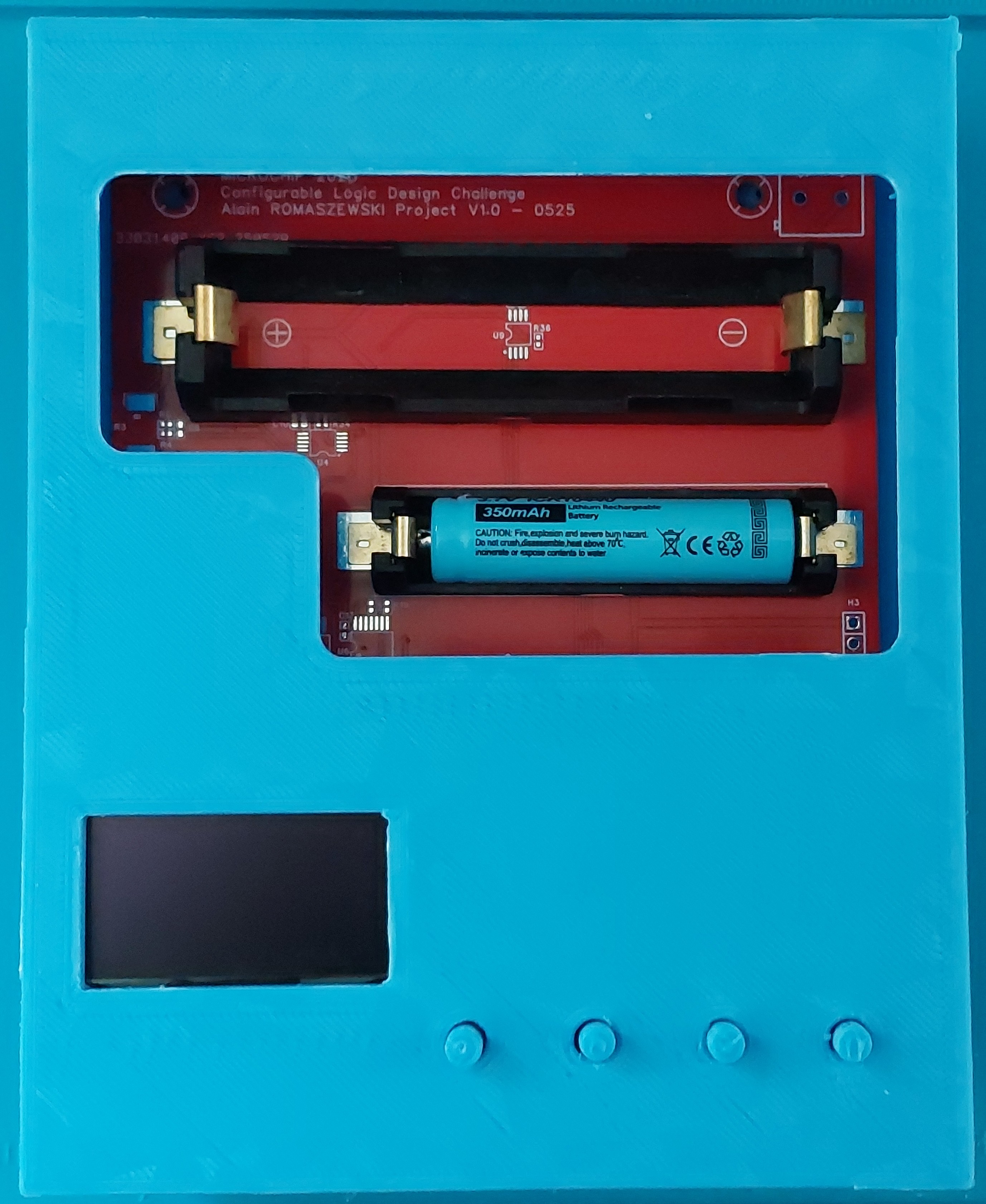
PCB assembled and fixed in the box
Here is a complete list and descriptions of the C functions in the program main.c, organized by categories:
String Utility Functions
reverse_string(uint8_t *str, int16_t length)
- Purpose: Reverses a character string
- Parameters: pointer to string, length
- Usage: Helper function for numeric conversion
int_to_string(int16_t num, uint8_t *str, int16_t index)
- Purpose: Converts an integer to string
- Parameters: number, destination buffer, starting index
- Return: new index after conversion
float_to_string(float value, uint8_t *result, int16_t precision)
- Purpose: Converts a floating-point number to string with specified precision
- Parameters: float value, result buffer, number of decimal places
Serial Communication Functions
printInt(uint8_t *s, int16_t d)
- Purpose: Displays a string followed by an integer on UART
- Parameters: character string, integer to display
- Usage: Memory-safe alternative to printf for embedded systems
prints(uint8_t *b)
- Purpose: Displays a character string on UART
- Parameters: pointer to string
- Usage: Simple output without formatting
I2C Communication Functions
I2C_read()
- Purpose: Reads 16-bit data from I2C register
- Global variables used:
i2c_addr, i2c_reg, nbwrite, nbread - Return: operation status (bool)
I2C_write()
- Purpose: Writes 16-bit data to I2C register
- Global variables used:
i2c_addr, i2c_reg, data - Return: operation status (bool)
Sensor Processing Functions
mcp9808_convert_temp(int16_t raw_temp)
- Purpose: Converts raw MCP9808 sensor value to temperature
- Parameters: 16-bit raw sensor value
- Return: temperature in degrees Celsius (float)
- Processing: Handles both positive and negative temperatures
read_button(void)
- Purpose: Decodes button states from ADC value
- Variables modified:
bt1, bt2, bt3, bt4, stbt - Principle: Uses resistor network to encode multiple buttons
Hardware Control Functions
clb1_swin_LOW(uint8_t num)
- Purpose: Clears a specific bit in CLB register
- Parameters: bit mask to clear
clb1_swin_HIGH(uint8_t num)
- Purpose: Sets a specific bit in CLB register
- Parameters: bit mask to set
Interrupt Management Functions
intclb1(void)
- Purpose: CLB1 interrupt handler
- Action: Activates emergency stop flag (
urgency_stop = true)
threshold(void)
- Purpose: ADC threshold interrupt handler
- Action: Calls
read_button() to process buttons
Battery Management Functions
setBatteryType(battery_type_t t)
- Purpose: Configures battery type and parameters
- Parameters: battery type (enum)
- Actions: Updates global parameters and optional screen
readVoltage(void)
- Purpose: Reads battery voltage via INA226
- Return: voltage in volts (float)
- Conversion: Uses 0.00125V per bit factor
readIntensity(void)
- Purpose: Reads charging current via INA226
- Return: current in amperes (float)
- Protection: Avoids values > 32767 (overflow)
State Management Functions
getChargingState(void)
- Purpose: Returns current charging state
- Return:
charging_state_t enumeration
getSystemStatus(void)
- Purpose: Returns current system status
- Return:
system_status_t enumeration
setSystemStatus(system_status_t s)
- Purpose: Sets system status
- Actions: Updates optional screen and displays in debug
clearSystemStatus(void)
- Purpose: Resets system status to STATUS_OK
Conversion and Calculation Functions
voltageToDAC(float voltage)
- Purpose: Converts voltage to DAC value
- Parameters: voltage in volts
- Return: 8-bit DAC value (0-255)
- Algorithm: Linear interpolation based on calibration
PID Control Functions
initPID(pid_controller_t *pid, float kp, float ki, float kd, int16_t min_output, int16_t max_output)
- Purpose: Initializes a PID controller
- Parameters: PID structure, Kp/Ki/Kd gains, output limits
calculatePID(pid_controller_t *pid, float setpoint, float measured_value, float dt)
- Purpose: Calculates PID output
- Parameters: controller, setpoint, measured value, sample time
- Return: limited PID output (int16_t)
Charging Management Functions
initCharging(void)
- Purpose: Initializes charging system
- Actions: Configures PID, temperature alerts, current limits
startCharging(void)
- Purpose: Starts charging process
- Actions: Enables power supply, configures DAC, enters CC mode
stopCharging(void)
- Purpose: Stops charging process
- Actions: Disables power supply, sets safety voltage
chargingControl(void)
- Purpose: Main charging control function
- Modes handled:
CONSTANT_CURRENT: Maintains constant currentCONSTANT_VOLTAGE: Uses PID to maintain voltageCHARGING_COMPLETE: Maintains final voltage
Safety Functions
safetyCheck(void)
- Purpose: Checks safety conditions
- Controls: Overvoltage, overcurrent, undervoltage
- Return: true if safe, false otherwise
BatteryPresent(void)
- Purpose: Checks battery presence and condition
- Return: true if battery OK, false otherwise
getChargeTimer(void)
- Purpose: Returns elapsed charging time
- Return: time in 500ms units (uint16_t)
Main Functions
main_charging(void)
- Purpose: Main charging management loop
- Sequence: Battery check → Initialization → Charging → Monitoring
- Exits: Charging complete, safety error, manual/timeout stop
main(void)
- Purpose: Main program function
- Sequence: System initialization → Battery selection → Charging
- Infinite loop: Waits for user selection then starts charging
The program uses two main conditional compilation directives that control which features are included in the final compiled code:
1. #define DEBUGVIEW
Purpose
This directive enables debug output functionality for development and troubleshooting.
Code Sections Affected
In setSystemStatus() function:
#ifdef DEBUGVIEW
    printInt((uint8_t *)"status: ",(int16_t)getSystemStatus());
#endif
- Action: When
DEBUGVIEW is defined, this code prints the current system status to the UART - Output: Displays "status: X" where X is the numeric value of the system status
- Purpose: Allows developers to monitor system state changes in real-time
In chargingControl() function (CONSTANT_CURRENT mode):
#ifdef DEBUGVIEW
    float_to_string(current_voltage,buf,3);
    prints(buf);
    float_to_string(current_intensity,buf,3);
    prints(buf);
    float_to_string(new_voltage,buf,3);
    prints(buf);
#endif
- Action: When
DEBUGVIEW is defined, this code outputs three key charging parameters - Output:
- Current battery voltage (3 decimal places)
- Current charging intensity (3 decimal places)
- New calculated voltage setpoint (3 decimal places)
- Purpose: Provides real-time monitoring of the charging algorithm's behavior during constant current mode
Effect When Enabled
- Adds serial debugging output
Effect When Disabled
- Removes all debug output code
- Reduces code size and improves performance
- Suitable for production builds
2. #define SCREEN (Currently Commented Out)
Purpose
This directive would enable support for an optional I2C display screen to show system information.
Code Sections Affected
In setBatteryType() function:
#ifdef SCREEN
    i2c_addr=SCREEN_ADDR;
    i2c_reg=SCREEN_REG_BAT_TYP;
    data=t;
    I2C_write();
#endif
- Action: When
SCREEN is defined, this code sends the battery type to the display - I2C Communication: Writes battery type value to register
SCREEN_REG_BAT_TYP (0x02) - Purpose: Updates the display to show which battery type is currently selected
In setSystemStatus() function:
#ifdef SCREEN
    i2c_addr=SCREEN_ADDR;
    i2c_reg=SCREEN_REG;
    data=s;
    I2C_write();
#endif
- Action: When
SCREEN is defined, this code sends the system status to the display - I2C Communication: Writes status value to register
SCREEN_REG (0x01) - Purpose: Updates the display to show current system status/error conditions
Hardware Context
#define SCREEN_ADDR         0x60    // address I2C of led screen
#define SCREEN_REG          0x01    // screen status
#define SCREEN_REG_BAT_TYP  0x02    // battery type
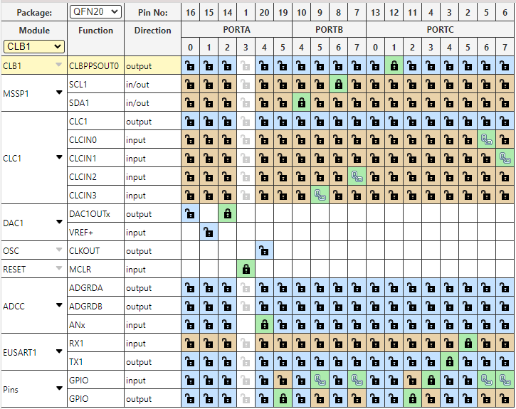
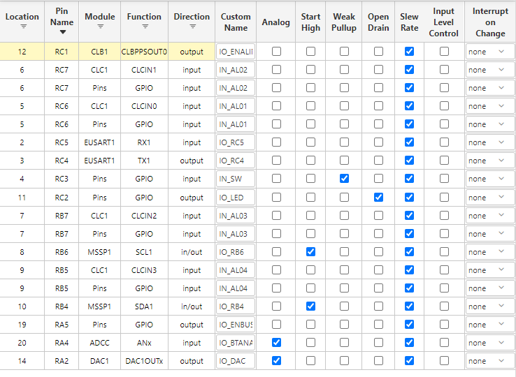
PINS CONFIGURATION
CONCLUSION
This multi-chemistry battery charging system represents a sophisticated approach to modern battery management, combining advanced microcontroller technology with precision monitoring and robust safety features. The integration of the 16F13145 microprocessor with specialized power management components like the MP1584 and precision monitoring devices such as the INA226 creates a highly capable charging platform that addresses the diverse requirements of contemporary battery technologies.
The system's ability to handle three distinct battery chemistries—Lithium-ion, LiFePO4, and Sodium-ion—positions it well for current and emerging energy storage applications. As the energy storage landscape continues to evolve, with sodium-ion batteries gaining prominence as a cost-effective and sustainable alternative to traditional lithium-based technologies, this charging system's adaptability becomes increasingly valuable.
The comprehensive safety architecture, utilizing both hardware-based protection through the CLC/CLB modules and software-based monitoring algorithms, ensures reliable operation across diverse operating conditions. The multi-layered approach to safety, combining temperature monitoring, current/voltage surveillance, and emergency stop capabilities, provides confidence in the system's ability to protect both the charging equipment and the batteries being charged.
The user interface design, featuring both local display capabilities and external communication options, makes the system suitable for both standalone applications and integration into larger energy management systems. The intuitive button-based chemistry selection combined with real-time status display provides users with clear operational control while maintaining the sophistication needed for professional applications.
From a technical perspective, the system demonstrates effective use of modern microcontroller capabilities, leveraging integrated peripherals like DACs, ADCs, and configurable logic modules to create a compact yet powerful charging solution. The precision voltage control through the 8-bit DAC and the accurate current monitoring via the INA226 enable implementation of optimal charging profiles that can extend battery life while maximizing charging efficiency.
This charging system architecture provides a solid foundation for future enhancements and adaptations. The modular design approach and comprehensive monitoring capabilities create opportunities for implementing advanced features such as battery health assessment, predictive maintenance algorithms, and integration with smart grid systems. As battery technologies continue to advance and new chemistries emerge, this system's flexible architecture ensures it can evolve to meet changing requirements while maintaining its core safety and performance characteristics.