This project is built around the PIC16F13145 Curiosity Nano board and represents a clock with a display on 4 8x8 LED matrices. Time recording is done with an RTC type MCP79400. In addition, this clock can also display the ambient temperature, thanks to the MCP9808 sensor.
Short description
This project represents a clock that can display the time (hours and minutes), the day of the week, the date (day, month and year) but also the ambient temperature.
The main element of the project is represented by the PIC16F13145 Curiosity Nano evaluation board; the clock is made with the MCP79400 RTC and the temperature is measured with the MCP9808 temperature sensor, all of these components being manufactured by Microchip.
The information is displayed on a combined display, made of 4 8x8 matrices, independently addressable, cascaded on an SPI bus.
The clock can be adjusted using three buttons: Up, Down and Set.
The data display on the dot matrix display is sequential: hh:mm --> weekday --> dd/mm --> /year --> temperature
IMPORTANT: this project contains several elements that make it different from other clocks, namely:
- the display is done on 4 matrix modules, 8x8 (detailed explanations and link, below);
- the RTC used is pin-to-pin compatible with a very used RTC (DS1307); that's why I used a "famous" board where I replaced the existing RTC with MCP79400 and made some modifications to make it work;
- I used 3 CLCs from PIN16F13145 to create a hardware debouncing of the three bits used to set the clock;
- now, perhaps the most interesting part of the project: everything that "happens" for reading/writing the RTC, the temperature sensor and displaying on the LED matrices takes place using the Timer0 interrupt; nothing is done in the Main loop.
A. MCU PIC16F13145 and PIC16F13145 Curiosity Nano board
The main part of this project is MCU PIC16F13145 (part on PIC16F13145 Curiosity Nano).
PIC16F13145 is a new generation MCU from Microchip's PIC16F13xxx family, based on the 8-bit PIC® Enhanced Mid-Range Core architecture.
Curiosity Nano for PIC16F13145 is a Microchip development board that includes:
- Pre-installed PIC16F13145 MCU
- Integrated debugger (via USB – no PICkit/ICD needed)
- USB power supply (5V -> 3.3V/5V switchable)
- Full pin access via side headers
- Support for direct programming from MPLAB X + MPLAB Xpress + MCC
- User LED (usually on RB5)
- User button
- Atmel/Microchip Data Gateway Interface (DGI) compatible interface – for debugging UART, I²C, SPI
B. Display
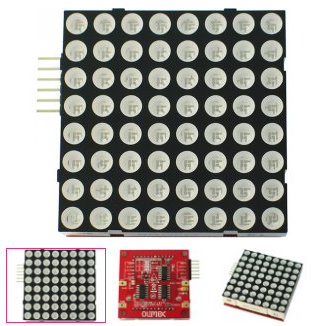
The display of this project is made using four 8x8 matrix modules, each matrix being accessed using an SPI interface.
The modules are these: MOD-LED8x8 - Open Source Hardware Board
Each module contain 2 74HC595 8-Bit Shift Registers With 3-State Output Registers and one ULN2003 + one BSS 138 FET tranzistor.
Datasheet for this moduile is attached.
OBS: one pair of 74HC595 8-Bit Shift Registers With 3-State Output Registers and one ULN2003 + one BSS 138 FET tranzistor can be replaced with one MIC5891, whether a PCB will be created for this project.
C. RTC
The MCP7940N is a Real-Time Clock (RTC) integrated circuit from Microchip that provides clock, calendar, and battery-backed timekeeping functionality. It communicates via I²C and includes a 32.768 kHz oscillator, internal EEPROM, and additional features such as alarms, timestamping, and power-fail detection.
The RTC does not automatically start the oscillator after power-on/reset. User must explicitly start it in software:
- the responsible bit is ST (bit 7 of the Seconds register – address 0x00).
- to start the oscillator, you must set this bit to 1.
OBS: If ST = 0 ⇒ the oscillator is stopped and the internal clock does not advance.
In order for the circuit to continue keeping time when main power is lost, you must:
- connect a battery to the VBAT pin.
- enable software support for VBAT by:
- setting the VBATEN bit (bit 3 of the Day register – address 0x03).
OBS: If you do not set VBATEN, the RTC does not automatically switch to battery when the main power fails.
The RTC stores:
- hour, minutes, seconds (registers 0x00 – 0x02)
- day of the week, day of the month, month, year (registers 0x03 – 0x06)
- all values are in BCD format.
OBS: the day of the week must be set by the user (1–7), it is not calculated automatically!
Important notes:
- the time format is 12h or 24h (bit 6 of the Hours register).
- MCP7940N detects power failure and can save the exact time at the time of interruption.
- it has no automatic correction mechanism for leap years or days depending on the month – the logic must be handled externally if needed.
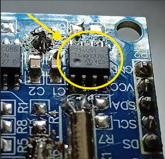
I have worked with this RTC in another project so I am somewhat familiar with it. When I started writing the code to access this RTC, I found this interesting document on the Microchip website, namely: Maxim DS1307 --> MCP7940N Migration (DS20002337B). This is where I got the idea to use a famous board, Tiny-RTC-DS1307-Module, with an RTC (DS1307) and a EEPROM (AT23C32). On this board I replaced the existing RTC with the one from Microchip, MCP7940N, I made a few modifications and everything worked from the first time, without any problems.
The modifications made to the Tiny-RTC board are the following:
- I eliminated the charging circuit of a battery, consisting of R5 and D1, in case it was present instead of a classic CR2032 battery;
- I eliminated R4 and R7;
- I replaced R6 with a wire;
- I replaced the DS1307 RTC with MCP7940N;
- I mounted a CR2032 battery.
Tiny-RTC board modified with MCN79400
Tiny-RTC schematic and picture
D. Temperature sensor
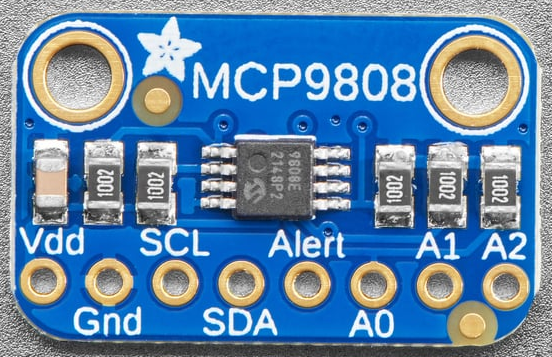
The MCP9808 is a high-precision digital temperature sensor manufactured by Microchip. It communicates via I²C and offers programmable resolution and advanced alarm and power management features.
Main features:
- very good accuracy: ±0.25 °C between -40 °C and +125 °C (typical)
- Measuring range: from -40 °C to +125 °C
- programmable resolution: fe to 0.5 °C (9 bits) to 0.0625 °C (12 bits)
General operation:
-the sensor returns the temperature in 16-bit digital format, stored in the Temperature Register (address 0x05);
- the value is encoded in 13 bits: bit 12 is the sign (0 = positive, 1 = negative); the rest represent the temperature value
Temperature extraction:
- read two bytes (MSB and LSB)
- conversion to °C according to the formula in the datasheet
The sensor used in this project is: https://www.adafruit.com/product/1782
For this project, the temperature is displayed with + and - sign.
MCP9808 temperature sensor
E. How does it work
As I mentioned at the beginning of this article, everything is done inside a PIC16F13145 MCU. It reads the RTC, the temperature sensor, the configuration buttons and displays the data on a display created from 8x8 matrix modules, individually addressable.
The IDE used for the development of this project is MPLABX V6.25 together with the XC8 compiler.
For the configuration of the peripherals, the MCC integrated in MPLABX was used.
To communicate with the RTC and the temperature sensor, an I2C bus is used and to communicate with the matrix display, an I2C interface is used.
The PIC16F13145 does not have two independent peripherals for I2C and SPI; only one can be active at a time, using the MSSP - Host Synchronous Serial Port Module.
In my case, first I started with the SPI configuration using the MCC in MPLABX. This is how I managed to communicate and display various information on the display, sending characters on SPI to the LED matrices. Then I tried to configure MSSP as I2C and this turned out to be something that I was unable to do, even after studying the official Microchip documentation. Maybe not everything is integrated in the MCC, who knows... During this time, I developed what is called SoftSPI, that is, a series of functions that communicate with my display just as if the MCU had the hardware SPI peripheral enabled. And I managed quite well.
Now, because I was unable to enable the hardware I2C peripheral, I resorted to the same solution: SoftI2C
At this point I can display various characters on the dot matrix display, I can read and display the RTC and the temperature. But, to set the RTC, I need to modify some variables, like time, date, etc.
For this, I will use 3 buttons, called Up, Down and Set.
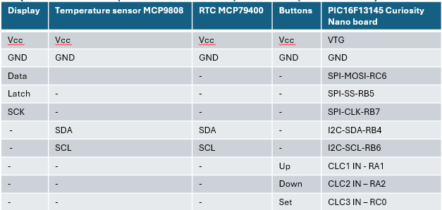
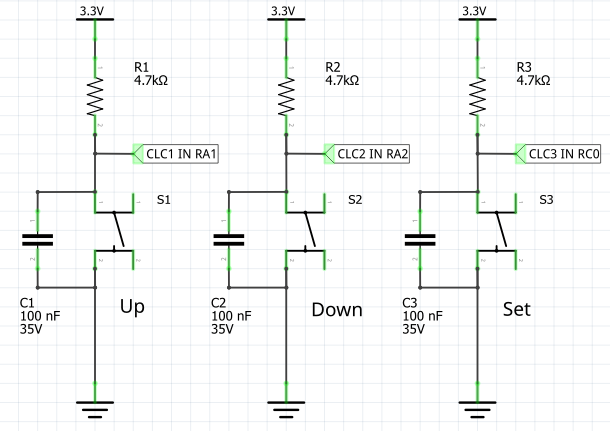
These 3 buttons are connected to the second input of 3 CLCs in the PIC16F13145 component, namely:
- RA1 - connected to CLC1 IN for button Up;
- RA2 - connected to CLC2 IN for button Down;
- RC0 - connected to CLC3 IN for button Set.
I used one CLC for each button to create what is called a "debouncing" function.
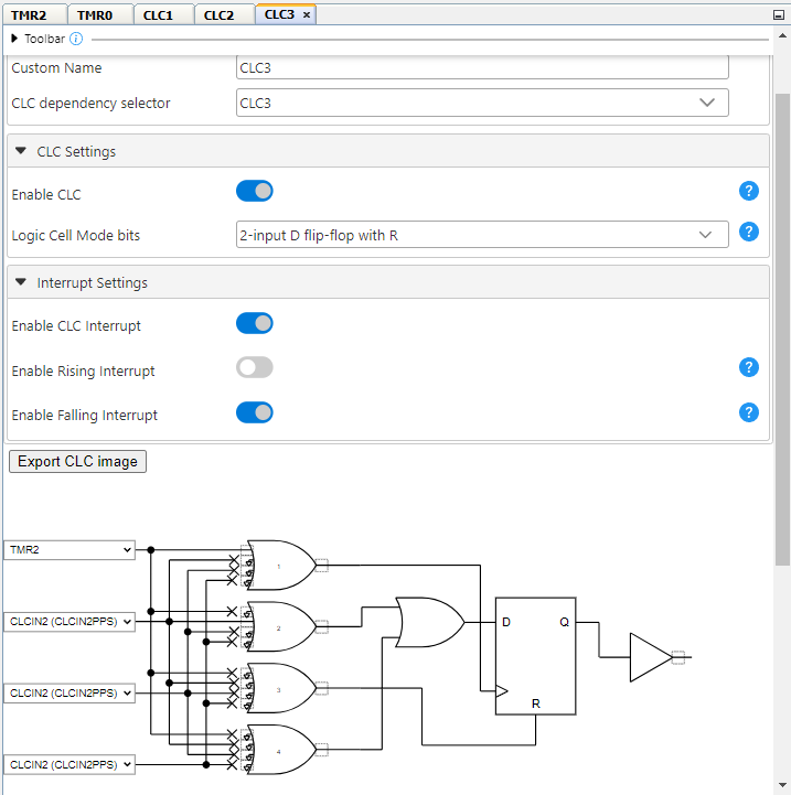
How I used the CLC: I configured it from the MCC as a "2-input D flip-flop with R"; then, I connected: the R pin (reset of the flip-flop) to logic "0"; the D input to the physical button (see above the button pins) and the clock input I connected to the Timer2 output, which is set to send a pulse every 2 milliseconds. Basically, if the clock is in "low" for 2 ms, any intentional or random presses generated by the button contacts will not be "passed" to the flip-flop output. I used the same configuration for the other 2 buttons.
In this way, I relieved the MCU of doing software debouncing.
Further: as I said at the beginning, everything happens in the ISR and Main does not contain any functions. So, for this to work, I created a function that does everything using Timer0, set to 1ms to generate an interrupt that will trigger the functios used to read/write RTCX, read temp sensor and update display.
But the display and reading time is maintained using another timer, Timer1, which deals exclusively with incrementing the 5 variables used to: update/refresh display, read RTC, read temperature sensor, "blink" effect for setting the RTC and "blink" effect for displaying the time with the ":" sign.
Current consumption is approximately 220mA at 5V
I made this project by connecting the various modules with jumping wires. I am also considering making a PCB that would contain all these elements but also a housing, maybe even a 3D printed one.
Summary of peripherals used in PIC16F13145:
- 3 timers: Timer0, Timer1 and Timer2;
- 3 CLCs, for buttons.
In this project, apart from the files generated by MPLABX, I created the following files:
- font_5x7.c - used to store the characters displayed on the display;
- rtc_mcp79400.c and .h - contain the specific functions for reading/writing the RTC;
- soft_i2c.c and .h - used for I2C communication;
- soft-spi.c and .h - used for SPI communication.
The application code is quite well commented and you can follow its operation without any problems.
UPDATE: I added the scroling mode!!!
How it is working: I created a string with the following configuration: " 13:22 Sun 29/06 2025 +23°C" from all data available; then I used the same buttons used for setting the RTC to enter/exit scrolling mode and to modify the text scrolling speed.
How to use the Set, Up and Down buttons:
* in static mode: Set is used to enter in RTC settings menu and Up and Down modify values;
* in static mode: Up or Down are used to enter in scrolling mode if I am not in the settings menu;
* in scrolling mode: Up and Down modify the scrolling speed; Set is used to enter in static mode.
For the scrolling mode I created a new project, Clock_02.X, which contains all the code so far but also the scrolling part. The code is attached. A video that demonstrates this mode is below in this project.
CLC3 configuration: the same for CLC1 and CLC2
The whole project: display led matrix, PIC16F13145 Curiosity Nano, Tiny-RTC modified, temperature sensor and buttons
Buttons used to program the RTC
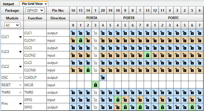
Pinout definition in MPLABX MCC
F. Next steps
I have reached the end of this interesting project. There were a few attempts that I went through, such as setting the CLKCs in the MCC, the unsuccessful attempt to activate the MSSP as I2C in the MCC, creating the SoftSPI and SoftI2C functions as well as the logic diagram of this project.
What would be the next steps:
- creating a PCB that brings all these components together;
- creating a suitable housing, possibly 3D printed;
- other ideas...the memory program is at 90%...I'll see..