This is a project of a garden watering system based on the CLB block. The circuit is designed to automatically water a garden. The watering system consists of 3 watering zones which should be open sequentially in order: zone 1, zone 2, zone 3 and stay open for configured time (i.e. 3 mins.). Periodically the ground's humidity is measured.
Solution
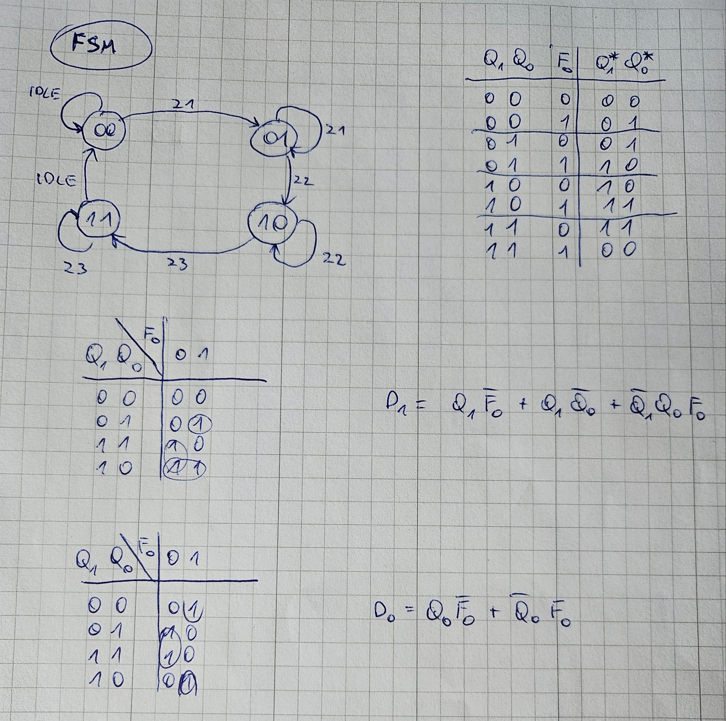
The CLB is clocked with TMR0 clock source. Each couple of clock ticks the ADC interrupt is triggered using the ADC’s auto triggering source set to CLB block. The period timer is generated by a clock divider implemented in CLB. In the interrupt the ADC values are read and depending on the threshold the CLB’s input bit is set or reset. The input bit triggers the watering sequence using the Finite State machine. The state of the FSM is decoded by the decoder and routed to enable each watering section. 2 LEDs are added to signal the current FSM state.
Elements
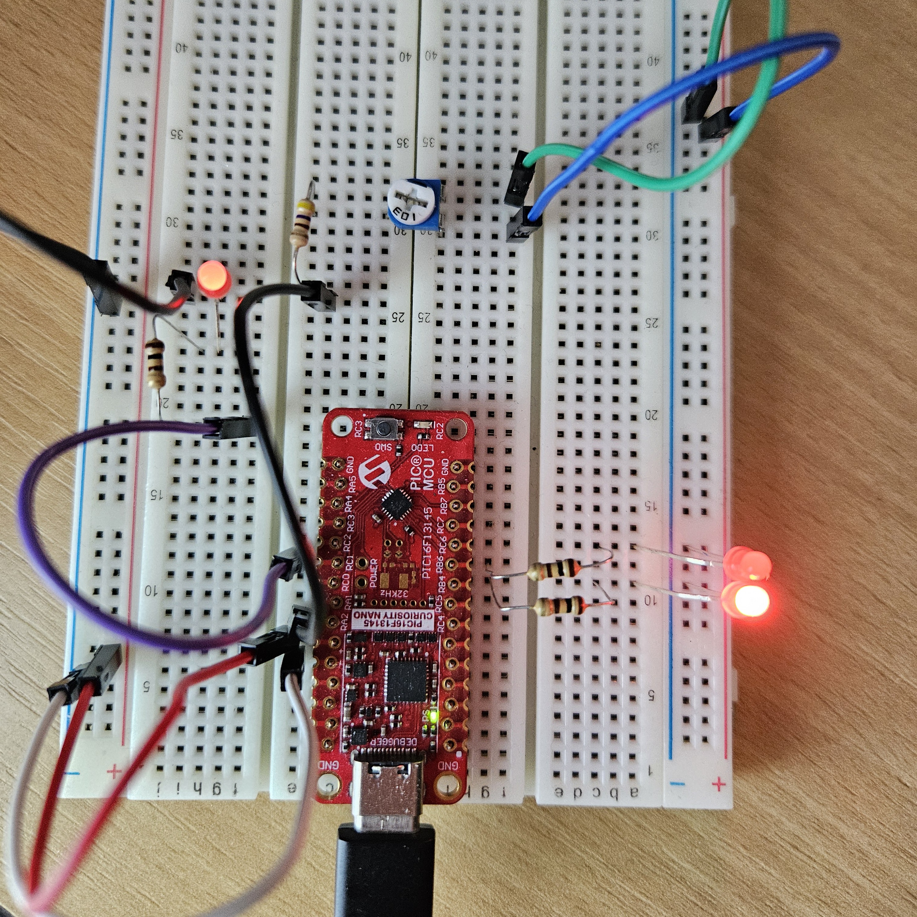
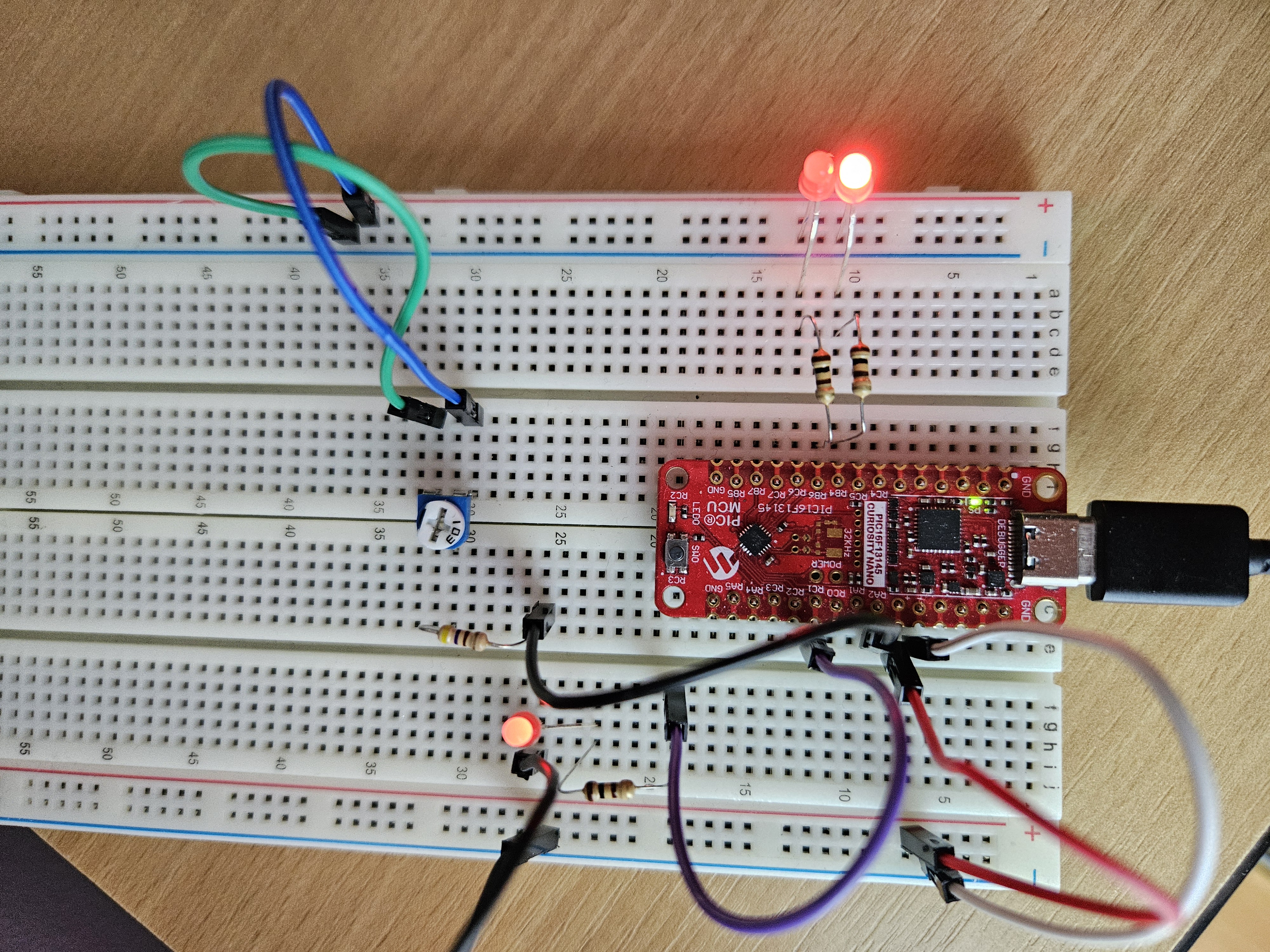
LED_ADC - indicating the ground humidity reading: dim - low value, bright - high value
LED_OUT1, LED_OUT2 - indicating the watering sequence
P1 - potentiometer to simulate the ground humidity sensor
R - current limiting resistors
To enable the watering screw the potentiometer P1 maximum to the right. It will cause the watering sequence to start. Screw the P1 to the left, it will cause the watering to stop.
How the CLB helped?
The CLB helped to incorporate core logic of the simple device and exclude it from the software code. Thanks to the CLB’s input and output internal connections it was possible to implement (almost) a functional device with minimal lines of code. The main clock source assures the device to work continuously without errors. The 32 BLEs allow to implement simple logic as described.
Development potential
The state machine can be improved to stop watering immediately after the requested humidity level is reached. Also the ADC interrupt is not very well synchronized with the input bit therefore the machine doesn’t stop at the switch off level.