This project presents a hardware-based stepper motor controller using the Configurable Logic Block (CLB) in the PIC16F13145 microcontroller. Inspired by the L297 IC, it eliminates external stepper driver logic by generating step sequences directly in the CLB.
What It Does
The controller replicates the behavior of the L297 stepper driver using only logic primitives—flip-flops, LUTs, multiplexers—within the PIC16F13145’s CLB. It does:
- Generates full-step or half-step drive signals entirely in hardware
- Supports
ENABLE, DIRECTION, and MODE inputs - Outputs stepper phases to motor drivers (e.g., L298) via PPS
- Fully autonomous operation after initialization—no CPU involvement during motion
- Frees the MCU core for tasks such as communication, sensing, or user interface
How the CLB was used
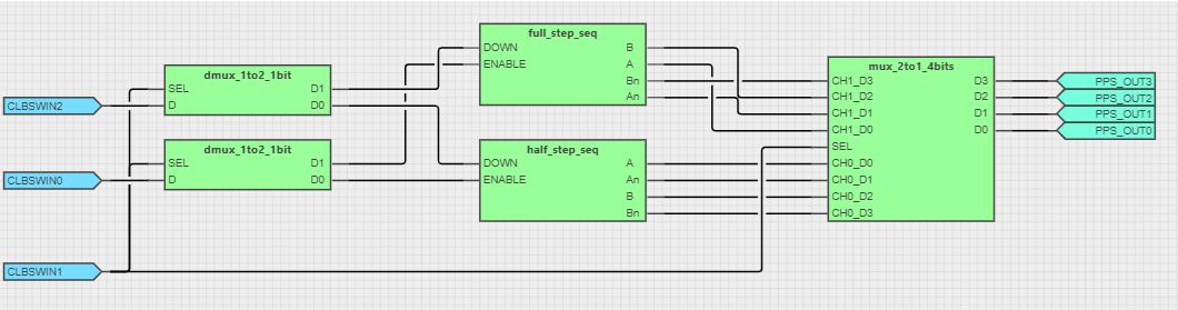
🔷 Main CLB Topology
Inputs (DIR, MODE, ENABLE) are routed through 1-to-2 demux blocks that activate either the full-step or half-step logic blocks. A 4-bit mux selects the correct output sequence for the motor driver pins via PPS.
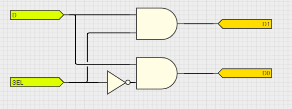
🔸 1-to-2 De-mux Module
Selectively routes control signals (e.g., DIR, ENABLE) to either the full-step or half-step block based on the MODE input.
🔸 2-to-1 4-Bit Mux Module
Chooses between the full-step and half-step sequences and drives the final motor phase outputs.
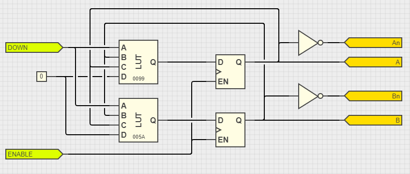
🔹 Full-Step Sequencer
Implements a classic two-phase stepper sequence using LUTs and flip-flops. Direction and enable signals determine state transitions.
🔹 Half-Step Sequencer
Generates an 8-state sequence for smoother motor operation. Uses more complex logic to alternate full and intermediate activation states.
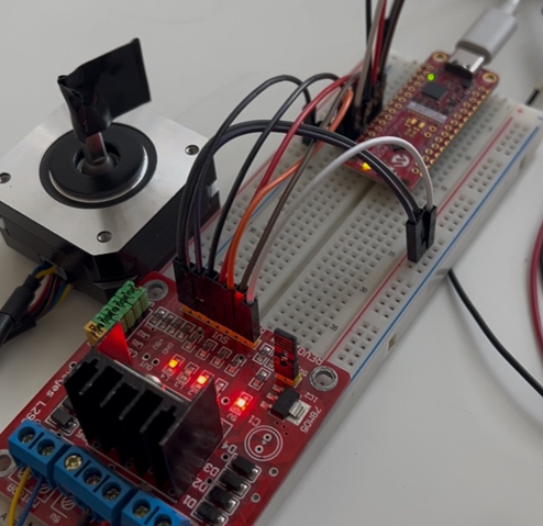
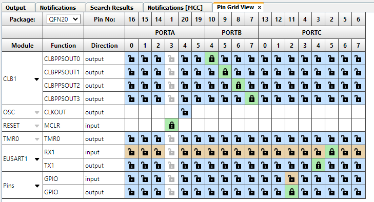
PIC16F13145 pin mapping
PortB pins RB4 to RB7 were used as output of CLB Stepper Motor control. The CLB is clocked by the Timer0. An serial interface was included to control the CLB inputs: enable (using the key 'e'), direction (using the key 'd) and mode (using the key 'm').
Testing and Validation
To verify the correct operation of the stepper motor controller, both visual observation and digital signal analysis were used:
- Stepper Motion Tests:
- The motor was run in full-step and half-step modes, with changes in direction and enable state tested in real time. The correct stepping sequences were visually confirmed by observing smooth and expected motor rotation patterns under various timing conditions.
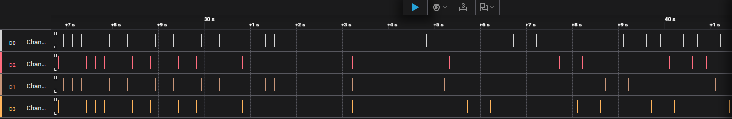
- Logic Analyzer Validation:
- A 4-channel logic analyzer was connected to the phase output pins (
PPS_OUT0–PPS_OUT3). The captured waveforms were analyzed to ensure: - Accurate phase transitions for both full-step and half-step modes
- Correct sequencing relative to the direction input
- Proper gating via the enable signal
- Clean, glitch-free signal generation synchronized with the Timer0 clock
These tests confirmed that the CLB-generated outputs matched the expected L297-style step sequences, validating both functional behavior and timing accuracy.
Conclusion
This project highlights the real-world utility of the PIC16F13145's Configurable Logic Block, demonstrating how embedded logic can replace external driver ICs. By implementing stepper control entirely in hardware, the solution:
- Reduces system cost (lower BOM)
- Minimizes CPU workload
- Frees the microcontroller for additional tasks (e.g., communication, HMI, sensing)
The approach is scalable, efficient, and ideal for smart peripheral applications or compact motion control solutions using low-cost microcontrollers.