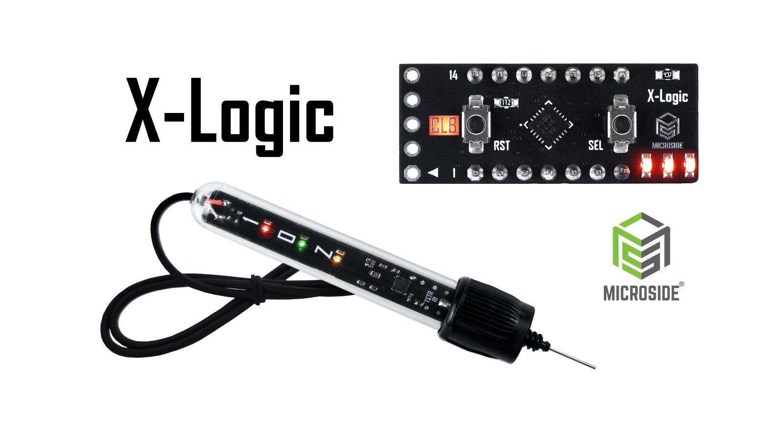
X-Logic consists of a pair of didactic and versatile tools: Digital Logic Circuit, a device that replaces up to eight logic integrated circuits with a single programmable unit, and Logic Tester, a tool designed to visualize the logic state of a circuit at any given point. A compact affordable solution for learning digital electronics.
What does X-Logic aim to do?
Digital electronics is a fundamental part of many STEM programs. However, teaching with logic gates and flip-flops often requires buying multiple physical ICs, which can make learning more complex, slower, and prone to wiring errors.
For decades, school labs have relied on the same logic gate ICs that, while functional, haven’t kept up with technology. These chips remain the educational standard, despite being outdated, bulky, and expensive when bought in quantity. Assembling even a basic circuit may require several ICs, overcrowding breadboards with wires, increasing costs, and slowing down the learning process.
X-Logic was designed as an alternative to these devices, offering many more features while still being affordable, it provides a compact and reusable solution for learning digital electronics, like combinational and sequencial circuits and even microcontrollers.
8-in-1 Digital Logic Circuit
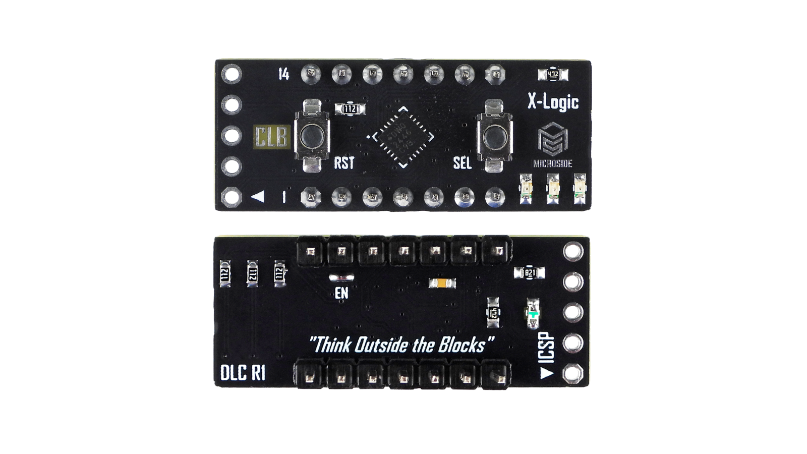
X-Logic: Digital Logic Circuit front and bottom
Digital Logic Circuit based on PIC16F13145 (VQFN-20) was created as a compact and cost-effective alternative. It integrates eight essential logic functions into a single module:
- Six quad gates (AND, NAND, OR, NOR, XOR, XNOR)
- Two dual flip-flops (D with Set/Reset and J-K with Reset)
It also features:
- Power and Function Indicators
- Reset and Function Selector buttons
- ICSP port to reprogram the device
The gates are implemented in the CLB using multiplexers, which guarantees an accurate, swift response to input changes, particularly in terms of timing, as it removes the need for CPU polling.
Implementation of the Logic Demux on the CLB
The flip-flops are implemented using the CLC with the aid of the CLB (to handle D-Flip-Flop Not Q), again, this helps to achieve better timing response, especially with high-speed signals.
Implementation of the D-Type Flip Flop on the CLC
Note: Full implementation details on the report at the end.
Thanks to our product validation process we've made our product easy to use, at first we planned a set of UART commands to configure the logic circuits in all kinds of ways. However, potential users found the process of configuration confusing, unclear and overcomplicated. Since our main objective is to replace logic gates ICs, we needed something that could match their simplicity. With this in mind, some changes were made.
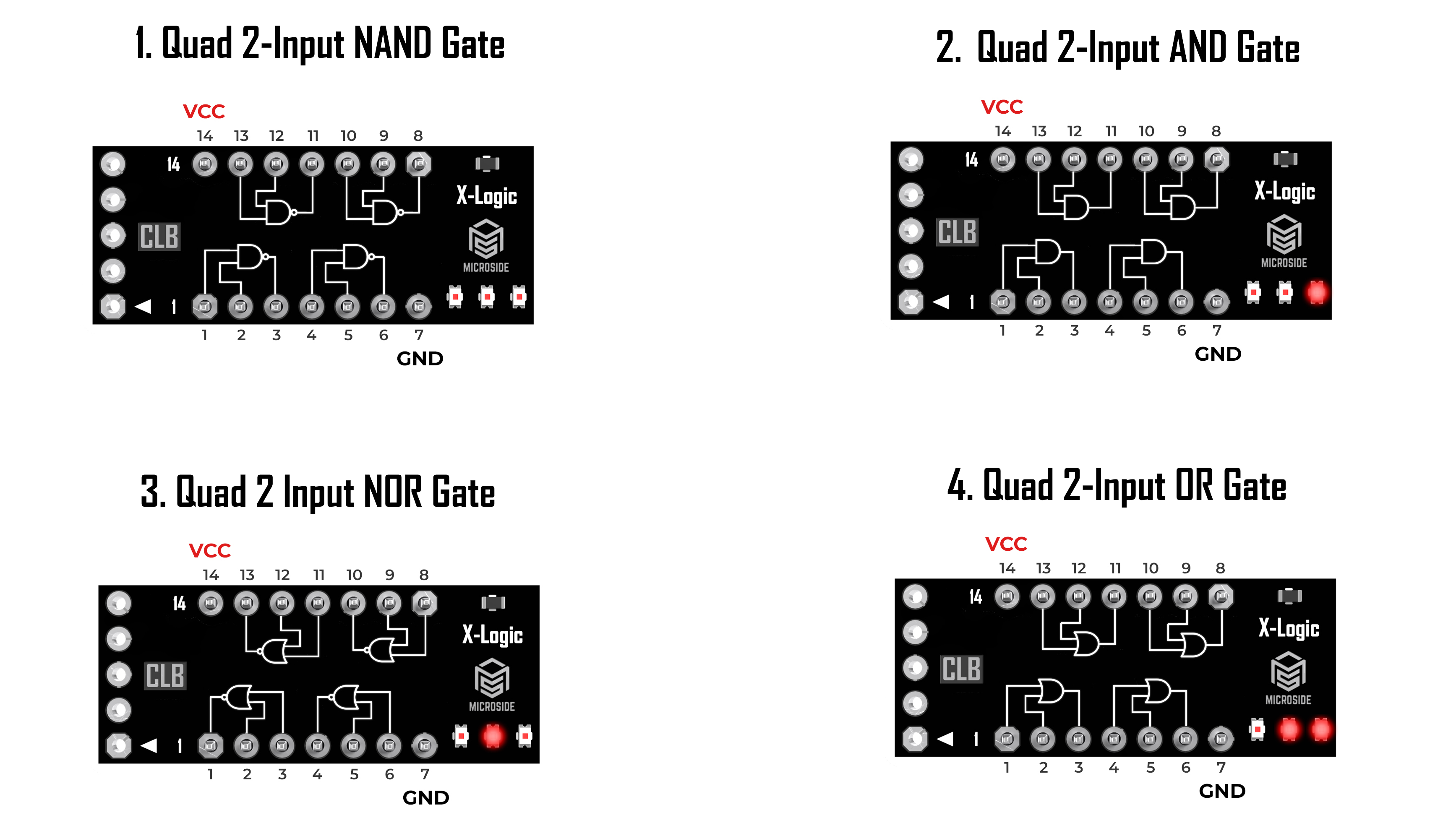
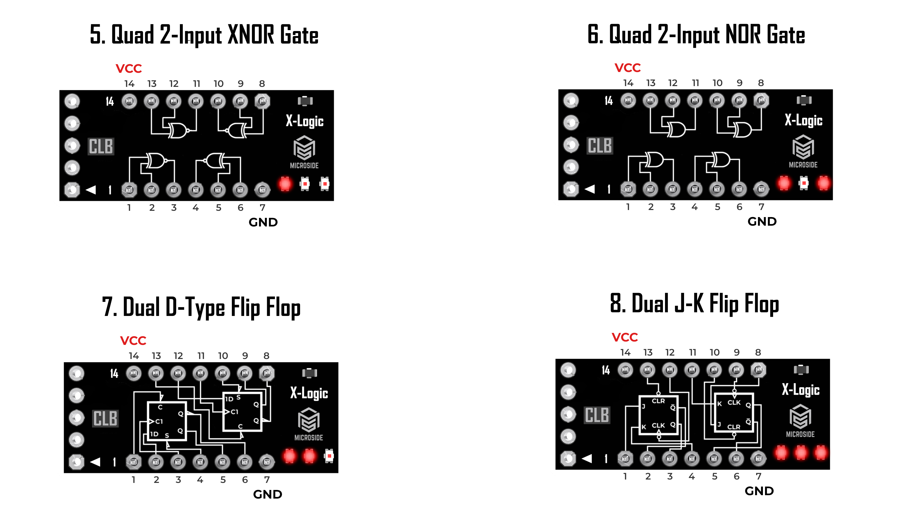
Now with the press of a single button, users can toggle the active function, with up to 8 available modes, making it easy to explore circuits without having to swap out chips:
X-Logic: Digital Logic Circuit - All modes available
This flexibility not only reduces the total number of ICs needed but also accelerates the learning and prototyping process.
Digital Logic Circuit is powered by Microchip’s PIC16F13145, an 8-bit MCU that features a Configurable Logic Block (CLB). This technology allows standard logic gates to be emulated within the microcontroller itself, with the added benefit of storing multiple configurations and selecting them dynamically. This approach compresses a large amount of logic within a single chip, simplifying integration of educational projects or functional prototypes without the need for multiple ICs. Furthermore, advanced users can modify or create new logic functions using graphical tools like the CLB Synthesizer, available in the Microchip ecosystem.
Beyond its function as a digital logic emulator, Digital Logic Circuit can also be used as a development board for the PIC16F13145, enabling more complex projects like interfacing with sensors, actuators, analog signals and more.
What is Logic Tester?
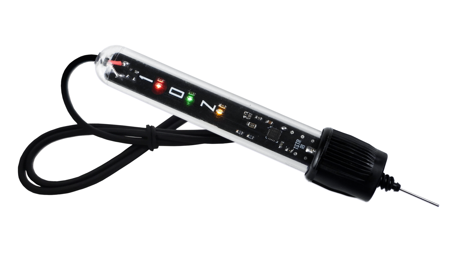
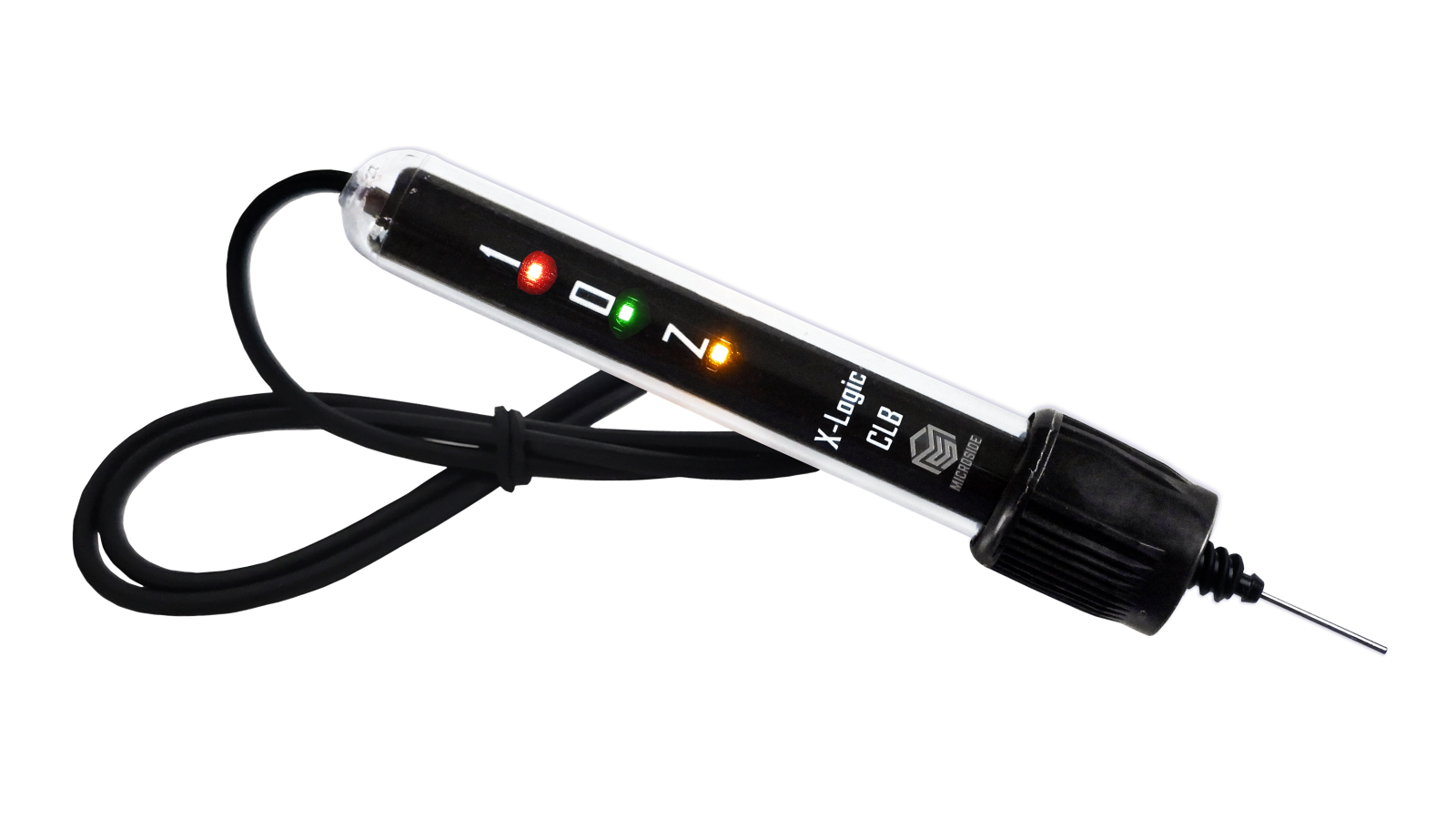
X-Logic: Logic Tester - probe front and bottom
Logic Tester based on PIC16F13145 (VQFN-20) is the perfect complement of Digital Logic Circuit, a tool designed to simplify reading the logic state of a signal at any point in a digital circuit. It allows users to identify whether signals are High(1), Low(0), or in a High-impedance (Z) state, making it an ideal tool for quick debugging on breadboards or development boards, especially during lab exercises or prototyping.
Its operation is based on analog comparators and the Configurable Logic Block (CLB) of the PIC16F13145, enabling precise detection with good response to high-speed signal changes.
Compact, efficient, and easy to use, Logic Tester simplifies diagnostics and enhances the understanding of how signals flow within a digital system.
First look at X-Logic
Check out this video explanation of how to work with X-Logic set of tools:
Available Now!
Get these devices through our online shop:
What's Next?
X-Logic: Digital Logic Circuit may be your first step on logic gates and flip-flops, but keep in mind that this device is based on Microchip’s PIC16F13145, which supports the CLB Synthesizer, a graphical tool that makes it easy to dive into programmable logic circuits. So its functionality can be extended to more complex cominational and sequencial logic applications.For example, take a look at how simple it is to implement a full adder on CLB Synthesizer, no code required just draw the circuit on the tool:
Full adder using NAND gates on CLB Synthesizer
For example, you can use a few Digital Logic Circuit as full adders to try to build an 8-bit full adder. There are also many planned updates from us for you to try like counters, demultiplexers, binary decoders, memory cells, adders and more...
Note: In order to reprogram Digital Logic Circuit you'll need a PIC Programmer compatible with MPLAB-X, like PICkit Basic.