Find out how to implement a one-button Bluetooth keyboard that takes input in the form of Morse Code
Below we described steps needed to understand how the solution has been programmed to create the wireless Morse code keyboard. However, if you just want to get the result of programming, download GreenPAK™ Designer software to view the already completed GreenPAK Design File. Plug the GreenPAK Development Kit to your computer and hit the program to design the device.
This project will discuss a one-button Bluetooth keyboard that takes input in the form of Morse Code. Morse Code is a scheme for sending messages using only short and long intervals, known respectively as dots and dashes. In this way, users can type any alphanumeric character using only a single input.
See Figure 1 for a Morse Code reference
The GreenPAK SLG46537V will be used to translate the Morse Code input into a byte of data. This byte will then be transmitted using an external Bluetooth module (specifically, the Rigado BMD-300) to be displayed as the appropriate character on a simple computer application.
External Components
The external components required for this application include a button for Morse Code input and a Bluetooth module to send the GreenPAK’s data to the computer application.
Button: This project uses an E-Switch KS-01Q-02 (Digi-Key EG4792-ND) through-hole pushbutton switch, though any momentary-on button would suffice.
Bluetooth: The Bluetooth module chosen for this application is a Rigado BMD-300 (Digi-Key 1604-1006-1-ND). There are significant price breaks when ordering in bulk, making this module an attractive low-cost Bluetooth option. For this project, a BMD-300 Evaluation Board (Digi-Key 1604-1007- ND) was used in order to simplify prototyping.
Realization with GreenPAK Designer
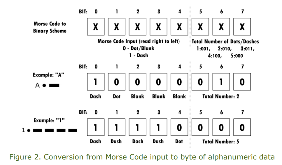
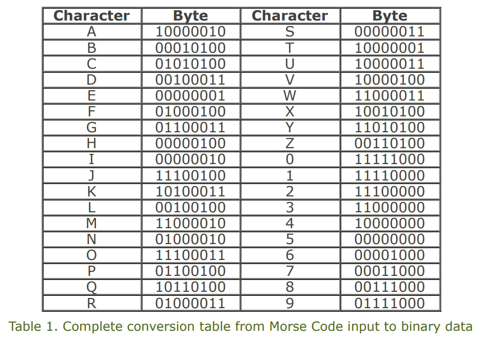
The first step in configuring the GreenPAK to serve as a Morse Code keyboard is to devise a method for encoding Morse Code input (dots and dashes) into binary data. To generate a unique byte of data from each Morse Code input, we’ll use the following scheme: Using this scheme, we can create a complete conversion table (Table 1).
With this scheme in hand, we can go on to describe the function of the GreenPAK with a state diagram.
Figure 3 displays this diagram as configured in GreenPAK Designer’s Asynchronous State Machine (ASM) Editor.
Figure 4 gives an overview of the connections configured in GreenPAK Designer, and highlights the various functional groups used in this design: Counters, Registers, Button Input, ASM, and Data Output. We’ll cover each of these groups in turn.
Asynchronous State Machine
We’ll begin by describing the ASM in further detail. There are eight states available in GreenPAK’s ASM, each of which has eight outputs and can take in as many as three inputs. The inputs control the state transitions, and the outputs will control the actions to be taken in each state. Both the inputs and outputs can be configured in the ASM Editor.
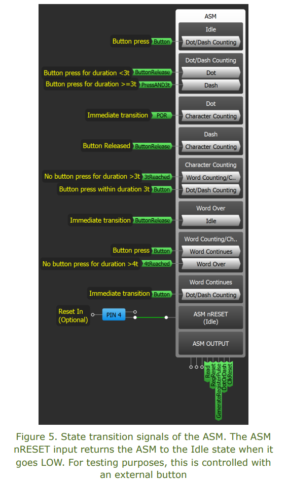
Figure 5 shows the states, state transitions, and state outputs in the main GreenPAK Designer workspace. This allows us to visualize both when a state transition will occur (when an input goes high), and which state the ASM will take next (the state connected to the input that has gone high). We can also visualize to which blocks the outputs are connected, which correspond to the actions that will be taken in each state. Table 2 gives a description of what actions should occur in each state.
The state outputs can easily be configured using the ASM’s RAM table in the ASM Editor (shown in Figure 6). The RAM table has been configured such that five of the eight possible outputs control the necessary actions in each state. These outputs are described in Table 3 and visualized in Figure 6.
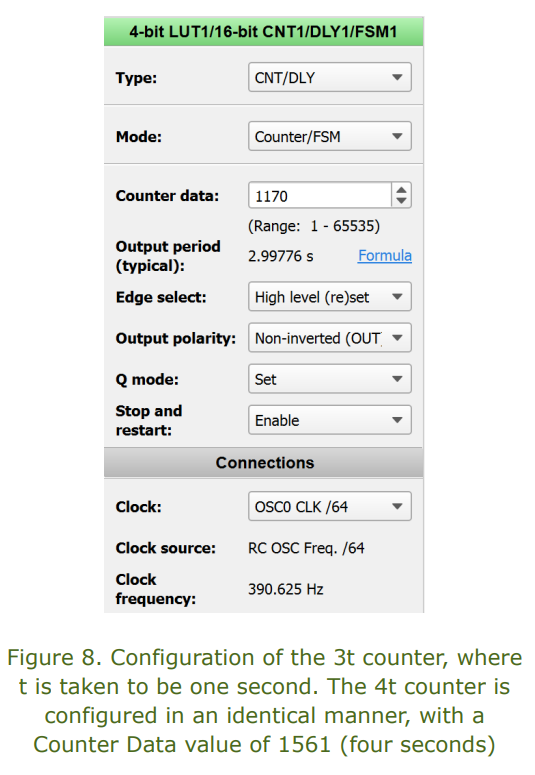
Now we’ll discuss the purpose and configuration of the blocks shown in Figure 7. First, to time the units of Morse Code, we’ll use the GreenPAK’s counter blocks in counter mode. Based on the state diagram shown in Figure 3, we’ll need one counter to time three units and another to time four. The configuration of the 3t counter is shown in Figure 8.
Two additional counter blocks are used in this application, both of which are configured to generate a one-shot pulse. This pulse serves as either a reset for the previous counter blocks, or as a way to advance the registers. Both one-shot counters are controlled via the ASM outputs described in Table 3.
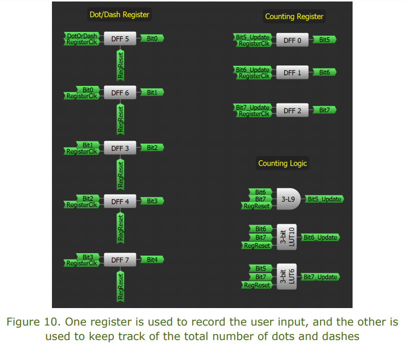
To keep track of the dots and dashes input by the user, we’ll create two separate registers using D Flip Flops (DFFs). The first register will consist of five DFFs and will record the sequence of user input. The second register will consist of three DFFs and will count the number of user inputs. Taken together, the registers will actively create the byte of Morse Code data as described in Figure 2.
The Dot/Dash register is comprised of five DFFs. The DotOrDash input to DFF 5 is set with the ASM output. The ASM outputs also control the RegReset (directly) and RegisterClk (indirectly, through the one-shot counter) inputs. To create the Counting Register, three Look-Up Tables (LUTs) are used to set the next binary value to be recorded.
In this way, each time RegisterClk advances the registers, the appropriate value is stored in the DFFs.
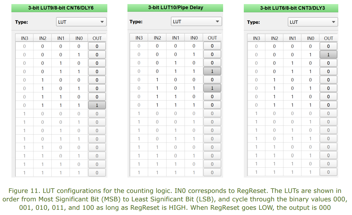
Furthermore, since we can design each LUT to require only two inputs, the third input can be set as RegReset – this lets us work around the fact that only the five DFFs used in the Dot/Dash Register have a direct reset input. The LUT configurations are shown in Figure 11.
Buttons
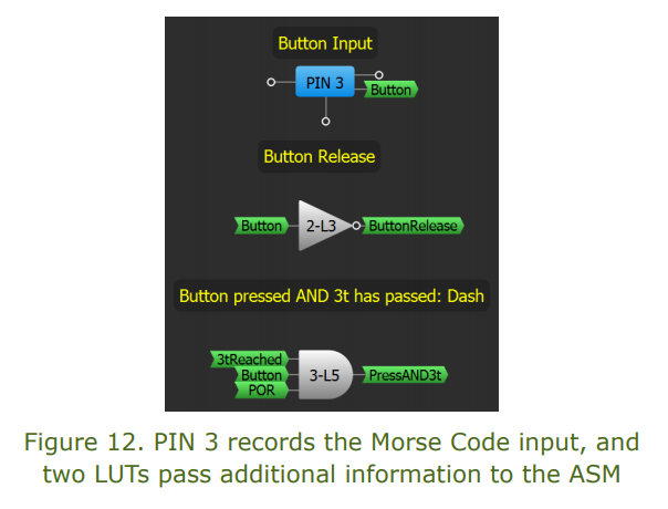
We’ll use PIN 3 as a digital input to record the user’s button presses. In addition, we’ll use another LUT (configured as an inverter) as a way to determine when the button has been released. One final LUT will be configured as an AND gate to determine when both the button is pressed, and the 3t timer has been reached.
The register data is passed directly to the Bluetooth module via output Pins 12-16 (dots/dashes) and Pins 5-7 (total number of dots/dashes). This data is only passed if the Read signal on PIN 17 is HIGH.
We can easily prototype this project using a breadboard, the GreenPAK Development Board, and the Bluetooth module’s evaluation board (discussed above in External Components). The prototype uses one button for Morse Code input and another as a reset to the ASM (optional). These inputs are taken from the breadboard to the GreenPAK Development Board, with the outputs taken from the GreenPAK Development Board to the Bluetooth module’s GPIO pins.
With this setup, the GreenPAK Designer emulation window should be configured as shown in Figure 15.
The next step is to configure the Bluetooth module to send the Morse Code data. The full steps of this process are beyond the scope of this project; however, full documentation (see here) is provided for the BMD-300 Bluetooth module should readers choose to use it if building this project.
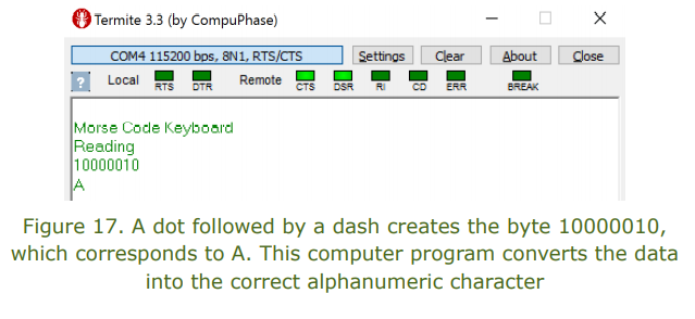
We can test the prototype by using the input button to type a character of Morse Code. Figure 17 shows the result of this test, using a simple computer program (source code attached) to look up the relationship between the byte of data and the appropriate character.
In the same way, we can test any of the other characters given in Table 1. Now, the computer program has been altered to allow for a continuous input of text (it will not display the binary data).
By using an external power source, we can test the current consumption of the prototype. The current consumption varies depending on its state. Its range is given in Table 4:
Extensions
This keyboard has a number of potential applications, such as an alternative to Smart TV text input (instead of the clumsy navigation of on-screen keyboards), or as a tool for handicapped keyboard input (due to its extreme simplicity). Both possibilities can make use of the same hardware while using the data in different ways. However, both could also extend the hardware to make use of an augmented or revised Morse code.
In this project, we built a low-cost, wireless keyboard that takes user input in the form of Morse Code. We used the GreenPAK SLG46537V ASIC to convert the user input into a customized binary format and then transmitted this data via a Bluetooth module for translation with a simple computer program. Hopefully, this project has demonstrated the versatility and ease of GreenPAK design.