Learn how to interface a 24V DC photoelectric sensor with an AC timer relay using an interposing relay in this practical industrial automation project.
Industrial automation often combines devices that operate on different voltages. A common example is using a 24V DC photoelectric sensor to trigger an AC-powered timer relay. Since these devices cannot be connected directly, an interposing relay is used to safely isolate the DC control circuit from the AC timing circuit.
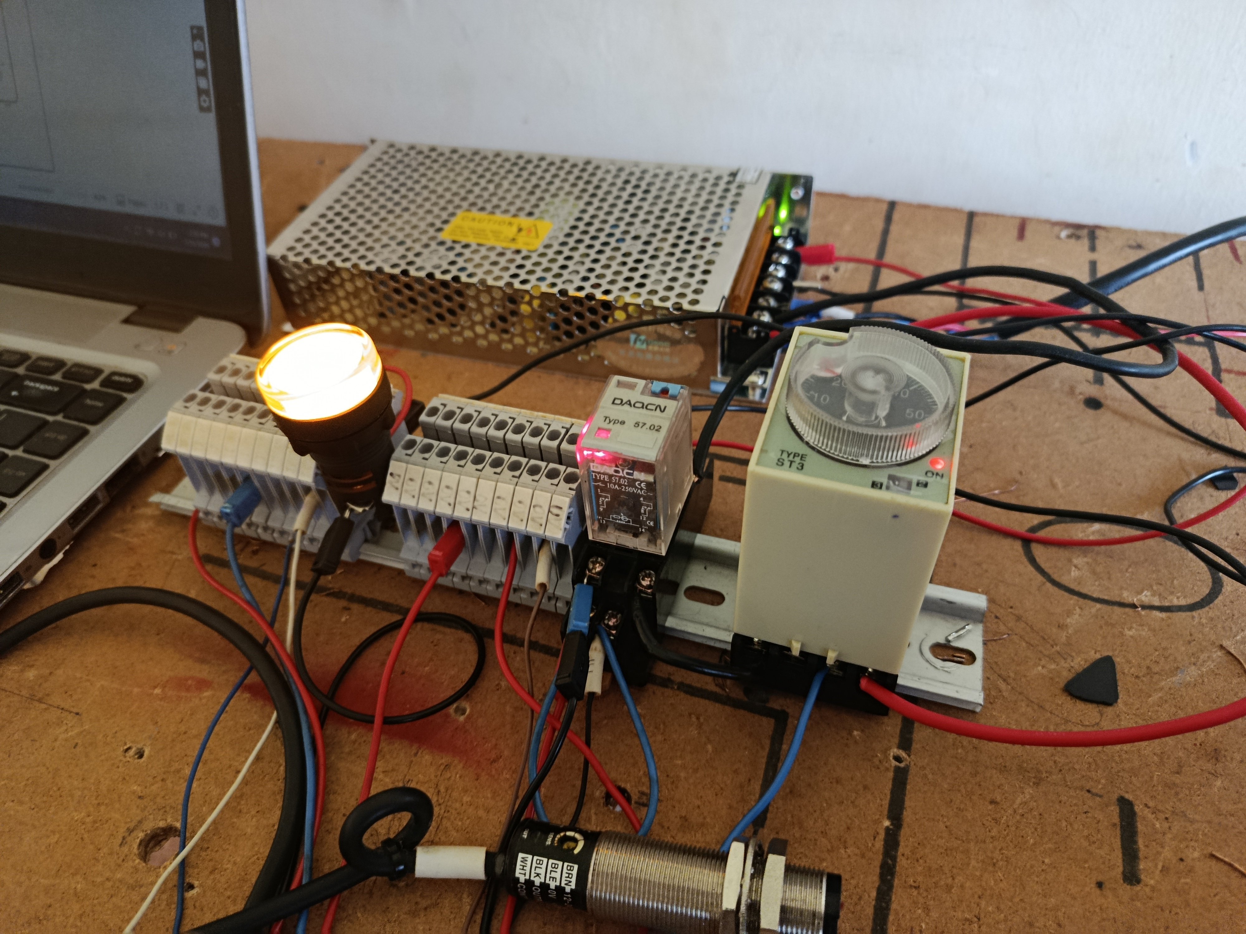
In this project, I built a complete demonstration panel showing how these components work together. The project is designed for students, maintenance technicians, and automation beginners who want practical experience with real industrial control wiring.
By the end of this build, you'll understand how a photoelectric sensor can initiate a timed sequence that could later be expanded to control motors, solenoid valves, conveyors, alarms, or other industrial equipment.
Watch the Project in Action
Before diving into the build, here's the complete video walkthrough of the project.
The video demonstrates every wiring connection, explains the function of each component, and shows how the completed circuit operates.
Why I Built This Project
Many beginners learn about sensors, relays, and timers separately, but struggle when they need to combine them into a complete control circuit.
One of the most common questions I receive is:
"How do I use a 24V DC sensor to control an AC timer?"
Rather than using a PLC, I wanted to demonstrate the traditional industrial approach that has been used in factories for decades.
This project introduces several important concepts:
-DC power distribution
-Terminal block wiring
-Photoelectric sensor connections
-Relay interfacing
-AC timer control
-Status indication
-Electrical isolation between AC and DC circuits
These are foundational skills for anyone interested in industrial automation or electrical control panel design.
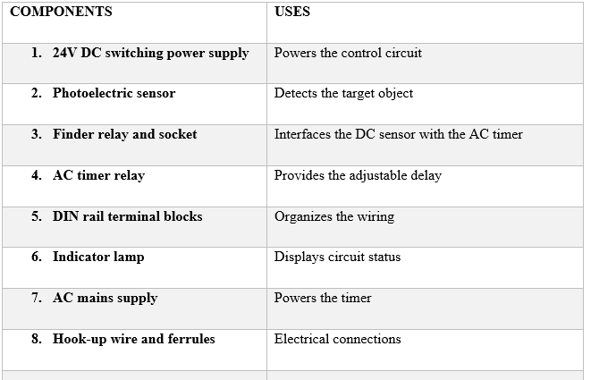
Components Used
The project uses readily available industrial control components.
Table 1. List of components used in the project and how they are used.
Project Overview
The control system is divided into two separate circuits.
24V DC Control Circuit
The DC side powers:
* Photoelectric sensor
* Relay coil
* Indicator lamp
This circuit operates at a safe control voltage commonly used in industrial automation.
AC Timing Circuit
The AC side powers only the timer relay.
The timer never receives power directly from the sensor.
Instead, it is switched through the relay contacts.
This separation keeps both circuits electrically isolated while allowing them to work together.
How the Project Works
The operating sequence is straightforward.
1. The power supply produces 24V DC.
2. The photoelectric sensor is energized.
3. An object passes in front of the sensor.
4. The sensor output activates the relay coil.
5. The relay changes state.
6. The AC timer receives power.
7. The timer begins counting.
8. After the preset delay, the timer output changes.
This same sequence is used in many industrial machines where an action must occur only after a short delay.
Wiring Highlights
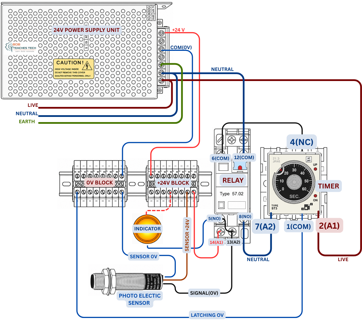
Rather than focusing on every terminal number, this project emphasizes understanding the function of each section of the circuit.
Figure 2. The completed wiring of the project showing how all the connections are routed.
Power Distribution
Separate terminal blocks distribute:
* +24V
* 0V
This creates a cleaner panel layout and makes future modifications much easier.
Sensor Connections
The three-wire photoelectric sensor uses:
Brown → +24V
Blue/white → 0V
Black → Switching output
The sensor output does not power the timer directly.
Instead, it controls the relay coil.
Relay Interface
The relay performs two important jobs.
First, it electrically isolates the sensor from the timer.
Second, it converts the low-voltage sensor signal into a switching action capable of controlling the AC timer.
Without this relay, connecting the sensor directly to the timer would not be appropriate.
Timer Circuit
Once the relay contact closes, the timer begins operating.
Depending on the timer model, the output can provide:
* ON delay
* OFF delay
* Interval timing
This project demonstrates a simple timed control sequence that can easily be adapted to many industrial applications.
Testing the Circuit
Once the wiring was complete, I performed several tests.
Sensor Detection
The sensor consistently detected the target object.
Relay Operation
Each detection energized the relay coil with an audible click.
Timer Response
The timer started immediately after the relay contact closed.
After the preset delay elapsed, the timer output changed exactly as expected.
Indicator Lamp
The indicator lamp provided immediate visual confirmation that the control circuit had energized.
This proved useful when testing and troubleshooting.
Practical Applications
Although this project is a training demonstration, the same concept is used throughout industry.
Typical applications include:
* Conveyor systems
* Packaging machinery
* Bottle filling equipment
* Automatic doors
* Product counting
* Material handling systems
* Sorting machines
* Labeling equipment
Once the basic circuit is understood, additional devices such as contactors, solenoid valves, buzzers, or PLC inputs can easily be added.
Lessons Learned
One of the biggest takeaways from this build is the importance of separating the control circuit from the load circuit.
Using an interposing relay provides:
* Better electrical isolation
* Easier troubleshooting
* Improved reliability
* Greater flexibility for future expansion
Another important lesson is the value of organizing the wiring using DIN rail terminal blocks. Even a relatively small project becomes much easier to understand and maintain when every conductor has a defined termination point.
Possible Improvements
If I were expanding this project further, I would consider adding:
* Emergency stop circuit
* Manual start and reset pushbuttons
* PLC monitoring
* Digital timer with LCD display
* Multiple sensors
* Conveyor motor simulation
* Counter relay
* Stack light indication
These additions would transform the project into a more advanced industrial training panel.
Final Thoughts
This project demonstrates a practical method of interfacing a 24V DC photoelectric sensor with an AC timer relay using an interposing relay. While the circuit itself is relatively simple, it introduces several fundamental industrial automation concepts that are applicable to much larger control systems.
For students and technicians beginning their journey into industrial control wiring, understanding how sensors, relays, timers, and power supplies interact is an essential skill that translates directly to real-world automation panels.
Complete Wiring Guide
This project article provides an overview of the build and its operation. If you'd like to see every wiring connection explained in detail-including terminal-by-terminal diagrams, troubleshooting tips, and a complete step-by-step walkthrough-you can read the full guide on Bob Teaches Tech:
Complete Guide: How to Wire a Photoelectric Sensor to an AC Timer Relay