Securely send messages locally, without using internet, phones, cell service, or any other centralized service.
ChatterBox is a completely off-grid, decentralized, secure text-based (for now) communication device that allows you to send and receive messages to between yourself and other people in your ChatterBox cluster.
ChatterBox Unique Features
Assembly
Be sure to take your time when assembling these. Installing a component incorrectly can easily ruin the kit. Once you have fully assembled the electronics, be sure to perform some continuity tests (instructions are shown), because if you have an incorrectly installed component or a short somewhere, you may fry any or all of the components as soon as you connect power (or worse, start a fire)! Building the enclosure/case requires a 3D printer. I used a Bambu Lab P1S, PLA with Carbon Fiber for the case back/mid, a metallic PLA for the front, and translucent PETG for the "window". See the PDF attached for all required components, I couldn't find all of them in the "assets" search of maker pro.
NOTE:
The instructions, as presented here, require a custom PCB I am working on making available but haven't yet made them available. If you are interested in this PCB, let me know and I will work it out somehow. I had them manufactured by PCBWay, but if there is interest, I probably need to get a lot made.
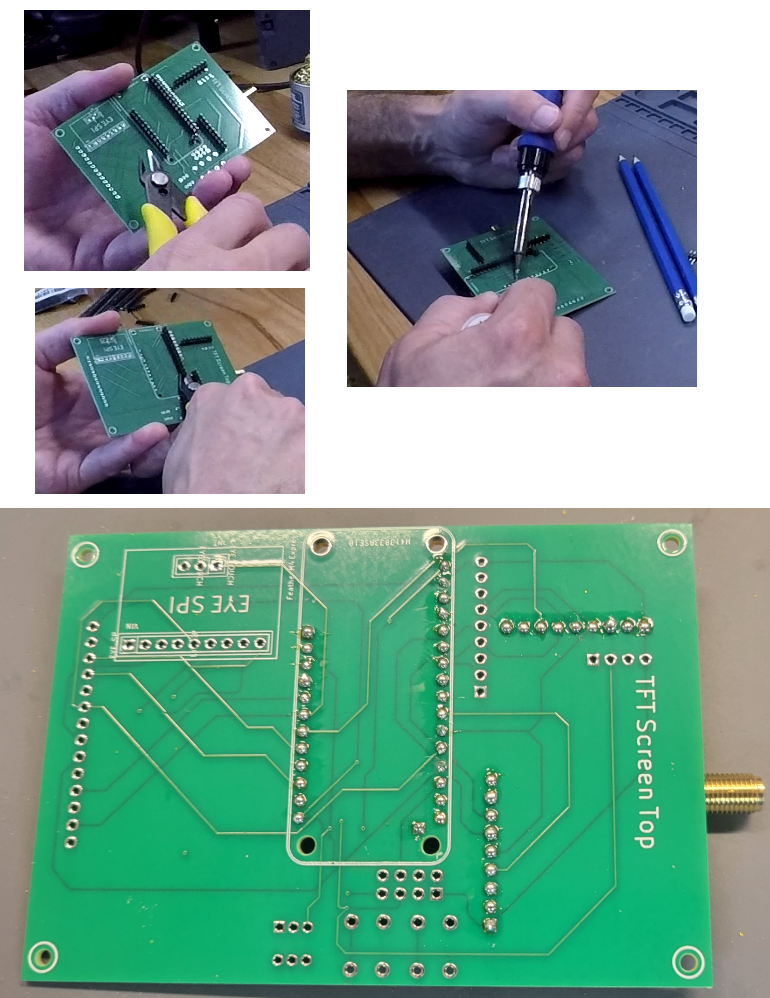
Solder the SMA antenna connector into place on the RFM breakout, careful not to short the antenna and ground posts.
Push two sets of appropriate length header pins through the section of the PCB that is for the M4. Set the custom PCB onto two pencils so it's elevated slightly, pins poking through the board and through the M4 Express, solder into place from above.
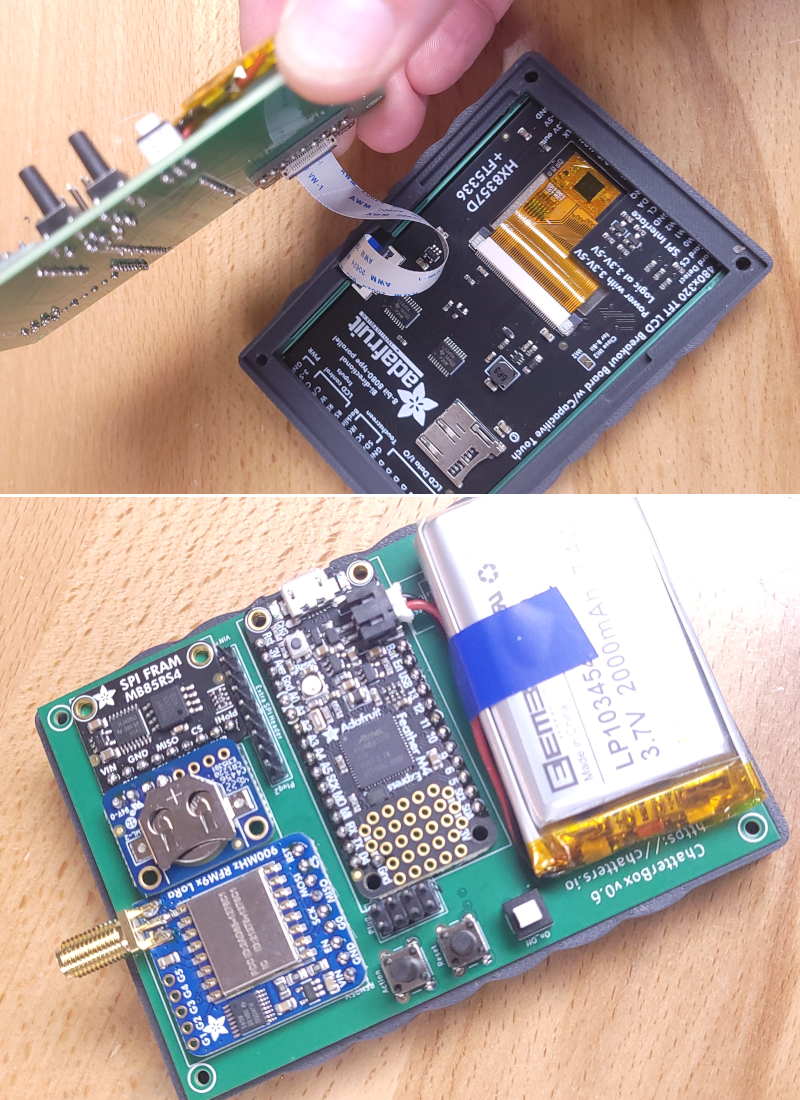
After soldering the M4 into place, the back of the PCB should look like this (don't forget that extra ground!).
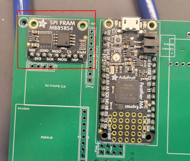
Slide header pins through the PCB, through the FRAM breakout, and solder from above.
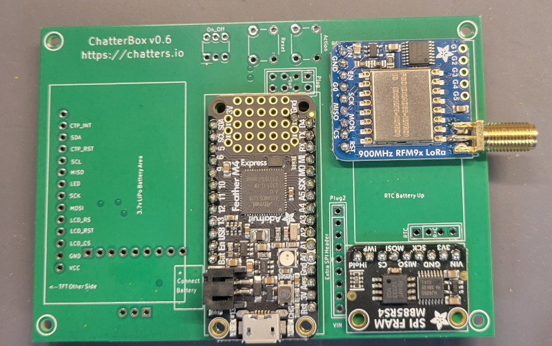
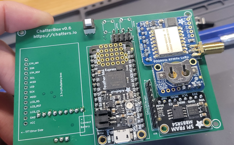
Install the RFM breakout into place. I put 3 sticky gorilla glue tabs in a stack between the RFM breakout and PCB to help elevate it and help it stay in place.
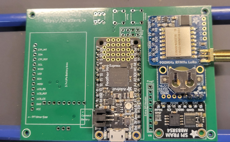
Set the header pins for the RTC into place (only 4 pins are connected, VIN, Ground, SDA, and SCL). Place the DS3231 onto the pins, as shown here. Solder the pins onto the DS3231.
Cut and solder the underside pins, leaving the PCB underside somewhat smooth as shown here. When you cut the pins, the component may come out of place. That's ok, just put it back and hold it in place until you have soldered a couple of pins to keep it there.
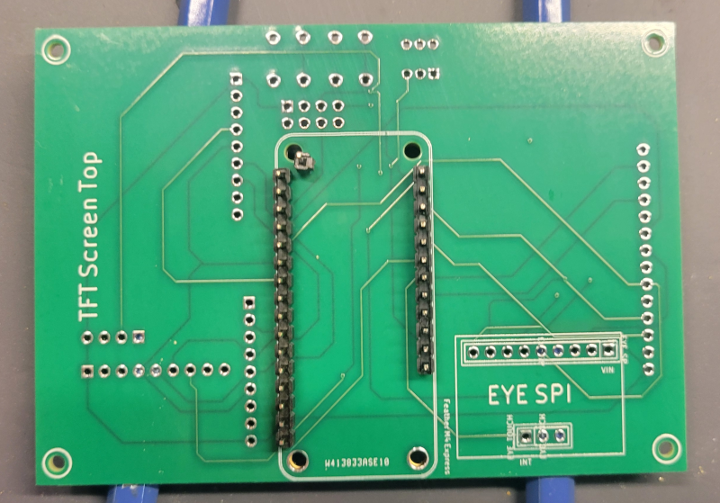
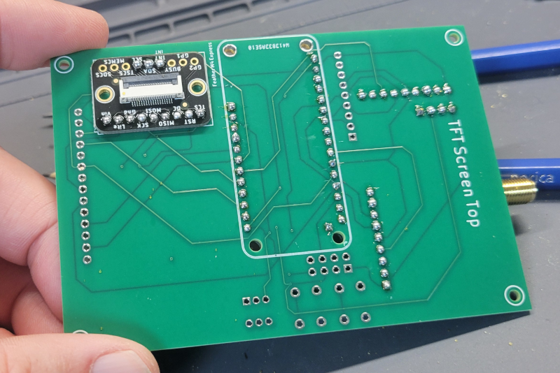
Install the eyespi breakout on the back side of the PCB, being sure to line up "int" on the breakout with "int" from the board.
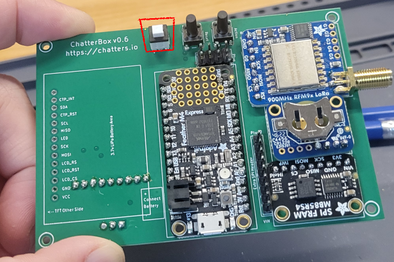
Install and solder into place the power switch and header pins (see PDF for compatible power switch). The hollowed out portion of the power switch should be facing the top / antenna end of the PCB.
Install and solder into place the momentary push buttons. See the attached PDF for compatible buttons.
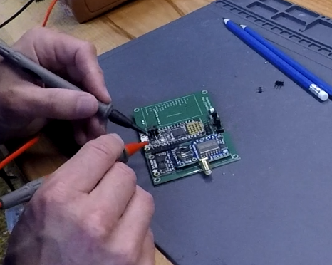
Continuity Testing
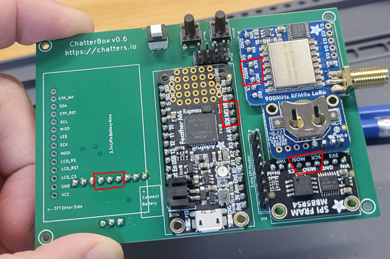
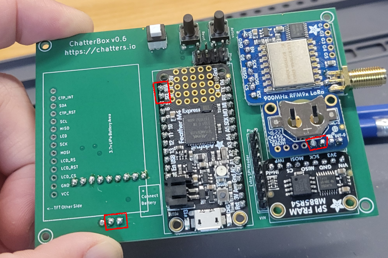
Put your multimeter into continuity test mode so we can check the connections and listen for beeps. First check that you have not shorted 3v3 and ground (that would be bad). Next, check each side-by-side pin and make sure there is no continuity. The only exception is the AREF and 3v3 pins on the M4 will have continuity.
Check the SPI connections. All SCK pins should have continuity with one another, same for MISO and MOSI.
Check the I2C connections. All SDA pins should have continuity with one another. The same goes for SCK.
Screen Connection
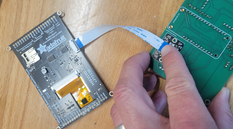
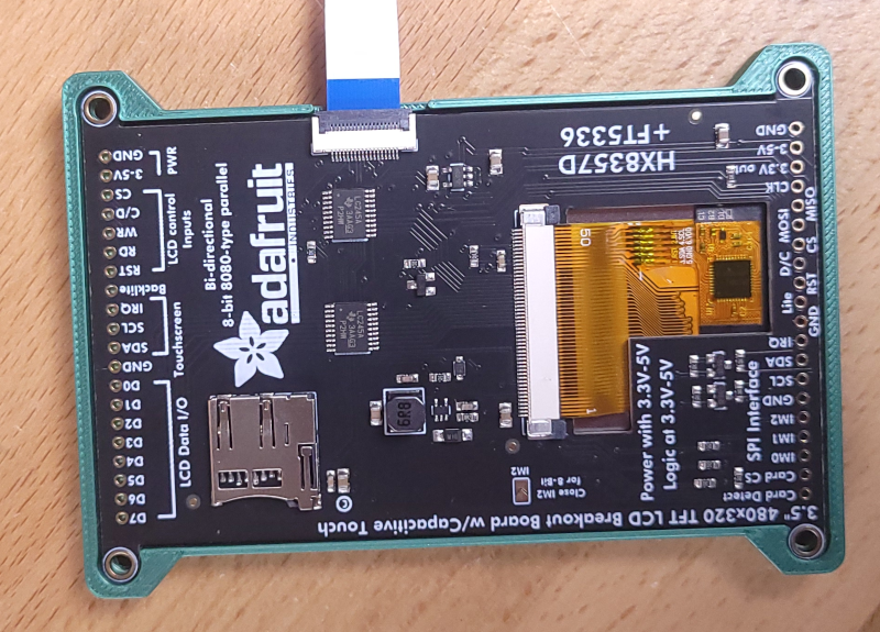
Use the display ribbon cable to connect the TFT display to the EYESPI breakout as shown. The tabs flip up (90 degrees) to open, and then press back down to lock the ribbon into place.
Firmware Setup
Instructions for firmware setup can be found at:
https://chatters.io/firmware
https://www.offgridcomms.club/help/chatterbox-firmware-samd51-version/
Make sure the power button is on the "ON" position (locked down). Unless, of course, you put the power button on upside down. In that case the on position will be up.
Connect a USB cable to your computer and the USB micro port of the M4. If all goes well, you should see the screen flashing and the colorful LED lighting up on the M4. If you don't see that, double-check the power switch. You may have installed it backwards.
Battery Install
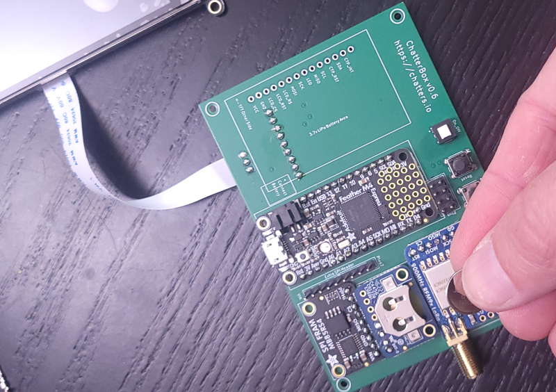
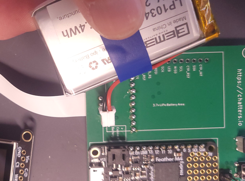
Install the 3.7 2000 mah LiPo battery. Be sure to check the continuity of the JST connector matches the M4 (shown on PCB). I like to tape the wire to the side of the battery as shown, to help it stay out of the way.
First Power Up (Cross your fingers!)
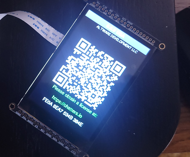
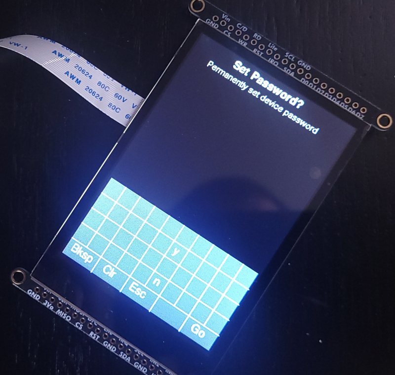
If the firmware is successfully installed, depending on the version of firmware you have obtained, it will either start up the ChatterBox (prompting you to decide if you want a password) or you may receive a QR code as shown here. If you receive the QR code, scan it to follow the instructions for obtaining a license.
If you see this screen, it means your firmware install is good and complete. You may now disconnect the power and move onto the enclosure.
Installing ChatterBox Into The Enclosure
The enclosure components can be 3D printed. I use a Bambu Labs 3D printer.
For the case back and case mid, I use PLA with carbon fiber. For the case front, I use whatever PLA looks nice and is the color I want. For the window, I use PETG translucent, so the colored light can show through.
The cad files are available for download at OnShape, and you can find links to them at https://chatters.io/build
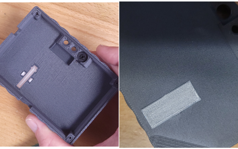
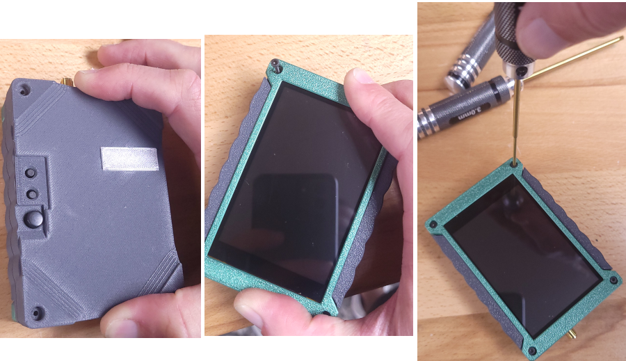
Snap the clear window/plug cover onto the back side of the case back. Also put the power button into place.
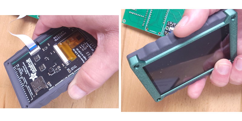
Press the TFT screen into the frame carefully, aligning the cutout with the ribbon cable.
Push the screen (and frame) through the mid case, as shown, so the mid case is aligned as it appears on the right, with cutouts aligned for the ribbon cable.
Press the case mid onto the front as shown.
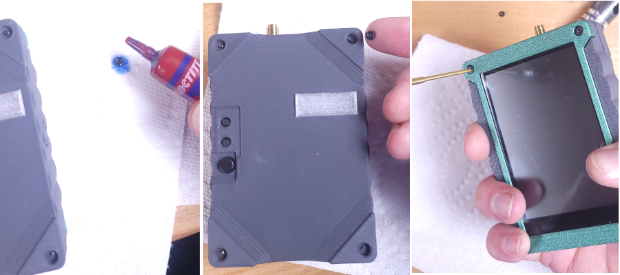
Position the assembled PCB over the case front and TFT as shown. The ribbon cable connectors will be on the same side of the two pieces. The ribbon cable will get a little bent up, but that's OK. The corner holes from the PCB should be nicely aligned with the corner holes for the case.
Push the case back into place carefully, aligning the buttons with the holes of the case back. Insert the M2 bolts into the 4 holes on the case front, and screw them down (don't tighten yet) just enough that you can see the threads starting to come out the back side.
Drip blue thread lock onto the nuts, use your finger to hold the nuts in place where you can see the threads coming out the back of the case, and then finish screwing the bolt into place (for all 4). Remember you are tightening this over PLA, so don't get it too tight, just quite snug. The thread locker should keep things together, rather than pressure.
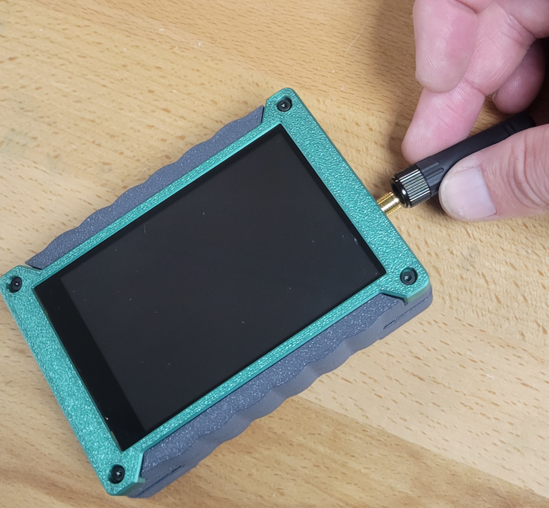
Install your antenna of choice. Be sure to install one that is tuned for 915 (assuming you're in the US).
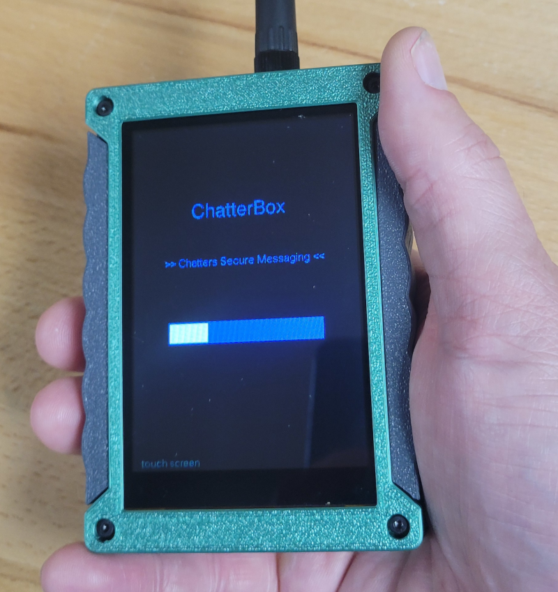
Power it up and start using it!
You can find setup instructions on https://chatters.io/setup or on the videos shown below.
ChatterBox Setup and Onboarding
To set up a new ChatterBox, simply choose if you want a password, a device name (I use my first name), a cluster name (up to 12 characters), a LoRa frequency (915.0 is usually just fine), and that's it.
For every remaining ChatterBox you want to be part of the cluster, give the device a unique name, leave the default generated cluster name/frequency, and then go through the onboarding process as shown below.
If you make any mistakes, you can always factory reset the devices and start over (Menu -> Device -> Factory Reset, or just hold the top button while the device powers up).
Cluster Deployment
I have not documented this process very well, but this is where it gets fun. You can experiment with different antennas, placing antennas/ChatterBoxes in different locations, and the mesh algorithm will make the best of whatever situation you give it.
Following This Project
Keep an eye on https://chatters.io or subscribe to the YouTube channel (you can find a link on the website, or just search YouTube for "chatterbox mesh". This is a quickly evolving and exciting project!
Quick Demo of the Mesh Capability
Tuning the Mesh Algo Using Simulations and Genetic Algorithm